
Power distribution cabinet convenient to move and power distribution cabinet convenient to brake

A technology for power distribution cabinets and cabinets, which is applied in substation/power distribution device shells, electrical components, substation/switch layout details, etc., which can solve the problems of inconvenient movement of power distribution cabinets and achieve the effect of slowing vibration

Inactive Publication Date: 2017-05-31
DONGMING POWER SUPPLY CO STATE GRID SHANDONG ELECTRIC POWER CO
View PDF4 Cites 4 Cited by
  • Summary
  • Abstract
  • Description
  • Claims
  • Application Information

AI Technical Summary

Problems solved by technology

[0005] The purpose of the present invention is to provide a power distribution cabinet that is easy to move, so as to solve the technical problem that the power distribution cabinet in the prior art is not easy to move

Method used


Image

  • Power distribution cabinet convenient to move and power distribution cabinet convenient to brake
  • Power distribution cabinet convenient to move and power distribution cabinet convenient to brake
  • Power distribution cabinet convenient to move and power distribution cabinet convenient to brake

Examples


Embodiment Construction

[0039] The technical solutions of the present invention will be clearly and completely described below in conjunction with the accompanying drawings. Apparently, the described embodiments are some of the embodiments of the present invention, but not all of them. Based on the embodiments of the present invention, all other embodiments obtained by persons of ordinary skill in the art without making creative efforts belong to the protection scope of the present invention.

[0040] In the description of the present invention, it should be noted that the terms "center", "upper", "lower", "left", "right", "vertical", "horizontal", "inner", "outer" etc. The indicated orientation or positional relationship is based on the orientation or positional relationship shown in the drawings, and is only for the convenience of describing the present invention and simplifying the description, rather than indicating or implying that the referred device or element must have a specific orientation, ...


PUM


Abstract

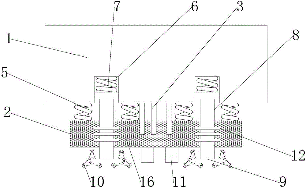
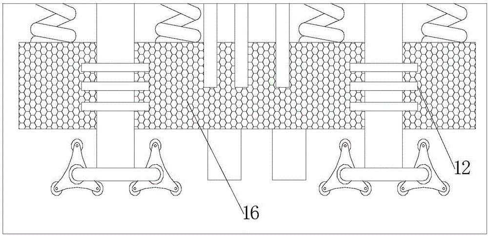
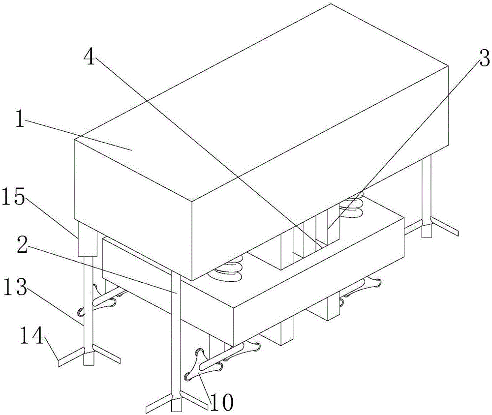
The invention provides a power distribution cabinet convenient to move and a power distribution cabinet convenient to brake, and relates to the field of the power distribution cabinet. The power distribution cabinet convenient to move comprises a cabinet body and a damping box; protruding parts are arranged at the bottom of the cabinet body; the damping box is filled with a damping agent; the protruding parts are inserted in the damping agent; a plurality of first damping springs are fixed between the cabinet body and the upper surface of the damping box; four inserting slots are formed in the lower surface of the cabinet body; second damping springs are arranged in the inserting slots respectively; one ends of the second damping springs are fixedly connected with the slot bottoms while the other ends are fixedly connected with one ends of crawling ladder wheel rods; the other ends of the crawling ladder wheel rods pass through the damping box to be rotationally connected with corresponding crawling ladder wheels; supporting legs are also arranged at the bottom of the damping box; and the distance from the supporting legs to the ground is less than an ultimate deformation length of the second damping springs. The power distribution cabinet convenient to brake comprises the power distribution cabinet convenient to move; and liftable supporting parts are arranged at the bottom of the cabinet body separately. By adoption of the power distribution cabinet convenient to move and the power distribution cabinet convenient to brake, the technical problem of inconvenience in movement of the power distribution cabinet in the prior art is solved.

Description

technical field [0001] The invention relates to the technical field of power distribution cabinets, in particular to a power distribution cabinet that is easy to move and a power distribution cabinet that is easy to brake. Background technique [0002] The power distribution cabinet (box) is divided into power distribution cabinet (box), lighting distribution cabinet (box), metering cabinet (box), and is the final equipment of the power distribution system. The power distribution cabinet is a general term for the motor control center. The power distribution cabinet is used in the occasions where the load is relatively scattered and there are few circuits; the motor control center is used in the occasions where the load is concentrated and there are many circuits. They distribute the electric energy of a certain circuit of the upper-level power distribution equipment to the nearest load. This level of equipment shall provide protection, monitoring and control of the load. ...

Claims


Application Information

Patent Timeline
Patent Type & Authority Applications(China)
IPC IPC(8): H02B1/30H02B1/52H02B1/54
CPCH02B1/306H02B1/52H02B1/54
Inventor 胡兆刚
Owner DONGMING POWER SUPPLY CO STATE GRID SHANDONG ELECTRIC POWER CO
Learn More