Cable erection structure of cable channel

A cable trench and cable technology, which is applied in the installation of cables and ground cables, can solve problems such as troublesome installation, and achieve the effects of simple structure, reliable support and low cost.

Active Publication Date: 2017-05-31
内蒙古自治区邮电规划设计院有限公司
View PDF4 Cites 0 Cited by
  • Summary
  • Abstract
  • Description
  • Claims
  • Application Information

AI Technical Summary

Problems solved by technology

[0002] The cables are mostly installed under the ground, and the support of the cables is completed by installing a bracket on the side wall of the cable trench, but this type of bracket in the prior art is installed separately. When installing several brackets, they need to be installed separately, which is troublesome to install

Method used


Image

  • Cable erection structure of cable channel
  • Cable erection structure of cable channel
  • Cable erection structure of cable channel

Examples


Embodiment 2

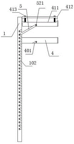
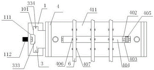
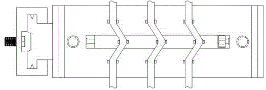
[0020] When in use, the bracket 1 is fixedly connected to the wall through the first screw 112, and then the slider 3 on the supporting plate 4 is inserted into the guide groove 101 to slide to the corresponding height to be installed, and then the bracket bar 5 is respectively inserted into the guide groove 101. In the insertion groove 102 and the first insertion groove 401 and fixedly connected by screws 521; cable fixing implementation 1: directly snap the cable 6 into the corresponding first buckle 407 and second buckle 406 to complete the preliminary Fix, and then screw the two second screws 413 on the top of the pressing plate 412 into the supporting plate 4 to complete the final fixing; cable fixing implementation 2: drive the screw 403 to rotate by turning the adjusting wheel 405, and control the sliding bar 404 along the adjusting chute 402 direction to slide, so that a certain angle is formed between the second buckle 406 on the sliding bar 404 and the first buckle 40...


PUM


Abstract

The invention discloses a cable erection structure of a cable channel. The cable erection structure comprises a bracket, wherein the bracket is vertically arranged; a guide groove is formed in the top of the bracket; the guide groove vertically penetrates through the bracket; embedding grooves are obliquely formed in front and rear side positions of the bracket; a sliding block is arranged in the guide groove; the right end of the sliding block extends to the outer part of the guide groove; the right end of the sliding block is matched with a supporting plate; first embedding grooves, which are matched with the embedding grooves, are formed in front and rear side positions of the supporting plate; and bracket strips are matched between the embedding grooves and the first embedding grooves. According to the device disclosed by the invention, the bracket is fixed firstly, then the supporting height of the supporting plate is adjustable through the sliding block, and the bracket strips can be supported between the supporting plate and the bracket to finish the supporting of the supporting plate, so that the reliability of supporting is ensured; and the bracket strips are embedded into the embedding grooves and the first embedding grooves, so that the relative rotation between the bracket strips and the supporting plate can be avoided, and the supporting is more reliable.

Description

technical field [0001] The invention relates to a cable trench cable erection structure. Background technique [0002] The cables are mostly installed under the ground, and the support of the cables is completed by installing a bracket on the side wall of the cable trench, but this type of bracket in the prior art is installed separately. When installing several brackets, they need to be installed separately, which is troublesome to install. Contents of the invention [0003] The technical problem to be solved by the present invention is to provide a cable trench cable erection structure. [0004] In order to solve the above problems, the present invention adopts the following technical solutions: [0005] A cable trench cable erection structure, including a bracket, the bracket is vertically arranged, the top of the bracket is provided with a guide groove, the guide groove vertically runs through the bracket, and the front and rear sides of the bracket are An embedding...

Claims


Application Information

Patent Timeline
IPC IPC(8): H02G9/02
CPCH02G9/02
Inventor 不公告发明人
Owner 内蒙古自治区邮电规划设计院有限公司
Why Eureka
Try Eureka