Light guide plate and backlight module

A technology of light guide plate and light incident surface, applied in the direction of light guide, optics, optical components, etc., can solve the problem of bright and dark lines affecting the optical appearance of the light guide plate.

Inactive Publication Date: 2017-06-06
RADIANT OPTO ELECTRONICS
View PDF2 Cites 5 Cited by
  • Summary
  • Abstract
  • Description
  • Claims
  • Application Information

AI Technical Summary

Problems solved by technology

The luminance effect produced by this kind of light guide plate with strip microstructure is better than that of light guide plate with dot structure, but it is easy to produce bright and dark lines and affect the optical appearance of the light guide plate

Method used


Image

  • Light guide plate and backlight module
  • Light guide plate and backlight module
  • Light guide plate and backlight module

Examples


Embodiment Construction

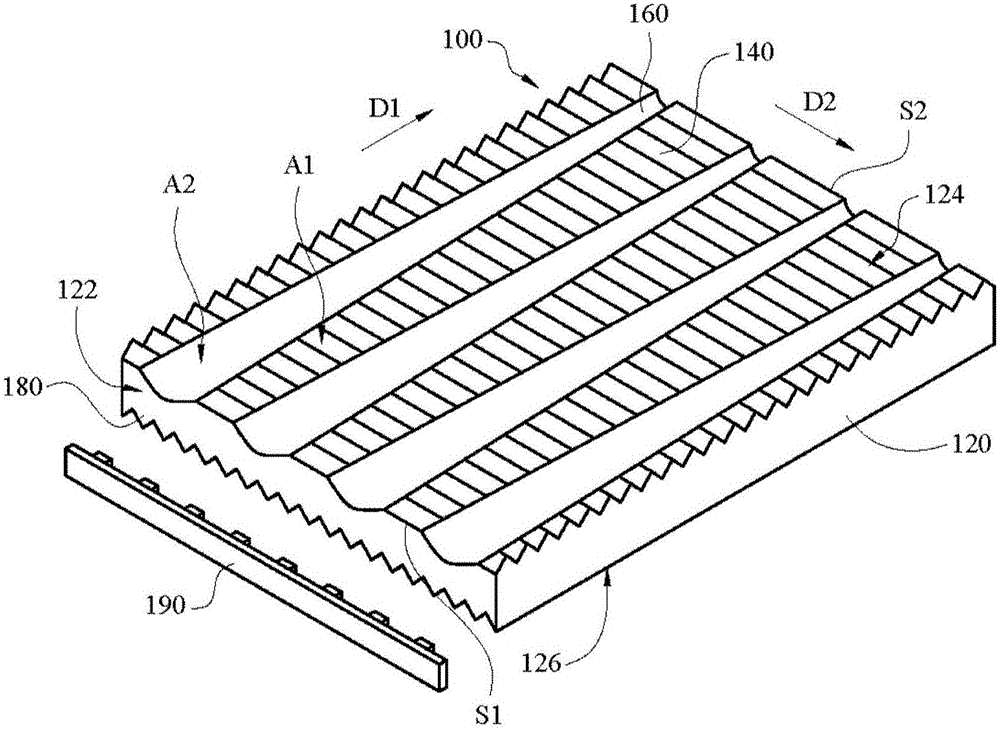
[0030] refer to figure 1 , which is a schematic structural view showing a light guide plate with an omnidirectional structure according to the first embodiment of the present invention. The light guide plate 100 of this embodiment can be applied to a backlight module (not shown). The light guide plate 100 may include a main body 120 and a plurality of microstructures, wherein the plurality of microstructures may include, for example, a plurality of first microstructures 140 and a plurality of second microstructures 160 . Through the first microstructure 140 and the second microstructure 160 disposed on the main body 120 , it is possible to simultaneously change and adjust the exit angle and optical trend of the light emitted from the light guide plate 100 .

[0031] In the light guide plate 100, the main body 120 can be a light-transmitting plate or other equivalent light-transmitting components. The main body 120 mainly includes a light incident surface 122 and at least one...


PUM


Abstract

The invention discloses a light guide plate and backlight module. The light guide plate includes a main body, a plurality of first micro-structures and a plurality of second micro-structures. The main body includes an incident surface, an emergent surface and a reflecting surface. The reflecting surface is opposite to the emergent surface. The incident surface connects the emergent surface and the reflecting surface. The first micro-structures are arranged on the emergent surface or the reflecting surface, and are arranged along a first extending direction. The second micro-structures are arranged on the emergent surface or the reflecting surface, and are arranged along a second extending direction. The second micro-structures and the first micro-structures are located on the same plane and intersect. Each second micro-structure is in a single strip form, and the width of each second micro-structure gradually decreases from one end close to the incident surface to the other end away from the incident surface.

Description

[0001] This application is based on the application number 201310369663.6, the application date is August 20, 2013, and the applicant is Ruiyi Optoelectronics Co., Ltd., which is a divisional application for the invention titled light guide plate with multi-directional structure. technical field [0002] The invention relates to a light guide assembly, in particular to a light guide plate and a backlight module. Background technique [0003] The light guide plate has a light incident surface, a light exit surface and a reflection surface. The light provided by the light source enters the light guide plate from the light incident surface of the light guide plate, and exits from the light exit surface of the light guide plate. In order to make the light sources passing through the inside of the light guide plate more uniformly mixed, microstructures, such as dot microstructures or strip microstructures, are usually provided on the light emitting surface or reflection surface o...

Claims


Application Information

Patent Timeline
Patent Type & Authority Applications(China)
IPC IPC(8): G02B6/00
CPCG02B6/0036
Inventor 张尹黄柏菖张智强张善富林信柏
Owner RADIANT OPTO ELECTRONICS
Why Eureka
Try Eureka