
Sweeping machine for photovoltaic panel

A cleaning machine and photovoltaic panel technology, applied in the cleaning method using tools, photovoltaic modules, photovoltaic power generation, etc., can solve the problems of high cost, complex structure of the cleaning machine, etc., achieve fast cleaning speed, easy control and maintenance, and save costs Effect

Pending Publication Date: 2017-06-09
济南纽兰数控机械有限公司
View PDF8 Cites 3 Cited by
  • Summary
  • Abstract
  • Description
  • Claims
  • Application Information

AI Technical Summary

Problems solved by technology

[0006] The technical task of the present invention is to address the above deficiencies and provide a cleaning machine for phot

Method used


Image

  • Sweeping machine for photovoltaic panel
  • Sweeping machine for photovoltaic panel
  • Sweeping machine for photovoltaic panel

Examples


Example Embodiment

[0037] Example 1:

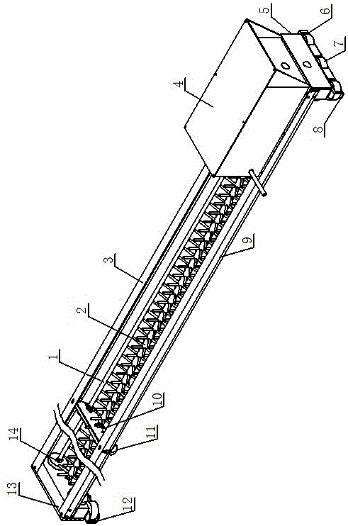
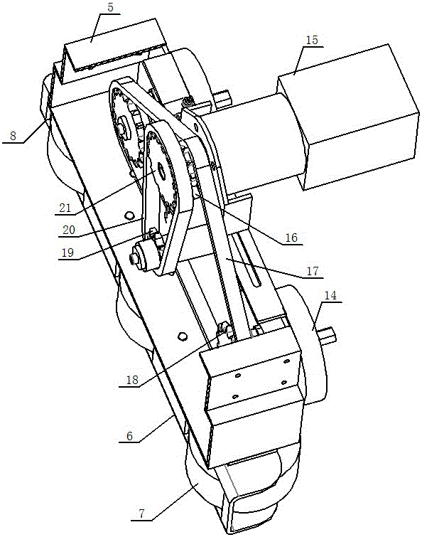
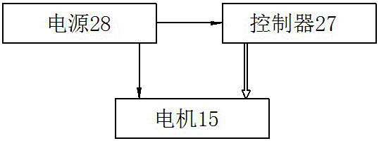
[0038] as attached figure 1 , attached figure 2 And attached image 3 As shown, a cleaning machine for photovoltaic panels of the present invention includes a frame, a rotatable brush stick 2 mounted on the frame, a rotatable drive shaft 1 mounted on the frame, and a The driving device on the frame, the power supply 28 and the controller 27, the transmission shaft 1 and the brush stick 2 are arranged in parallel, and the two ends of the transmission shaft 1 are equipped with traveling wheels 14 respectively; the driving device is located at one end of the frame, including a motor 15, Driving sprocket I21, driving sprocket II16, driven sprocket I19, driven sprocket II18, chain I20 and chain II17, motor 15 is arranged on the frame, driving sprocket I21 and driving sprocket II16 are coaxially arranged on the motor On the output shaft of 15, the driven sprocket I19 is assembled on one end of the brush stick 2, the driven sprocket II18 is assembled on one en...

Example Embodiment

[0045] Example 2:

[0046] as attached image 3 , attached Figure 4 And attached Figure 5 As shown, this implementation is a further improvement on the basis of Embodiment 1. The difference between this embodiment and Embodiment 1 is: both ends of the brush stick 2 are equipped with drive sleeves, and each drive sleeve is equipped with a brush Traveling wheel; the driving device also includes a driven sprocket III23 with the same diameter as the driven sprocket II18, the driven sprocket III23 is located between the two driven sprockets II18, and the driving sprocket II16, two driven sprockets II18 and the driven sprocket III23 are connected through the transmission of the chain II17, and the driven sprocket III23 drives the driving sleeve close to it to drive the brush walking wheel 22 close thereto. The synchronous cooperation of two brush walking wheels 22 can prevent the brush stick 2 from supporting the bottom in the walking process.

[0047] The end of the brush sti...


PUM


Abstract

The invention discloses a sweeping machine for a photovoltaic panel, and belongs to the field of devices for sweeping photovoltaic panels. The technical problem that a sweeping machine for the photovoltaic plate is complex in structure and high in cost are solved. The sweeping machine structurally comprises a rack, a rotatable brush roll assembled on the rack, and a driving device arranged on the rack. A transmission shaft is further assembled on the rack, and the transmission shaft and the brush roll are arranged in parallel. Walking wheels are assembled at the two ends of the transmission shaft respectively; the driving device can drive the transmission shaft to rotate to achieve walking of the walking wheels, and can drive the brush roll to rotate to achieve sweeping of the brush roll. A controller and a power source are further arranged on the rack, the power source is connected with the controller, and the driving device is connected with the controller. The sweeping machine is simple in structure and convenient to operate and maintain.

Description

technical field [0001] The invention relates to the field of devices for cleaning photovoltaic panels, in particular to a cleaning machine for photovoltaic panels. Background technique [0002] A photovoltaic panel module is a power generation device that generates direct current electricity when exposed to sunlight. It consists of thin, solid photovoltaic cells almost entirely made of semiconductor materials such as silicon. Since there are no moving parts, it can be operated for a long time without any wear and tear. Simple photovoltaic cells power watches and calculators, and more complex photovoltaic systems light homes and power the grid. Photovoltaic panel assemblies can be made in different shapes, and the modules can be connected to generate more electricity. Photovoltaic panels are used on roofs and building surfaces, and even as part of windows, skylights or shading devices. These photovoltaic facilities are usually called building-attached photovoltaic systems. ...

Claims


Application Information

Patent Timeline
IPC IPC(8): B08B1/04H02S40/10
CPCH02S40/10B08B1/002B08B1/04Y02E10/40F24S40/20Y02E10/50
Inventor 李佳解辉
Owner 济南纽兰数控机械有限公司
Learn More