Pressure touch sensor, display device and drive method for same

A touch sensor and display device technology, applied in piezoelectric/electrostrictive/magnetostrictive devices, instruments, semiconductor devices, etc., can solve problems such as pressure-sensing misidentification

Active Publication Date: 2017-06-09
BOE TECH GRP CO LTD
View PDF6 Cites 16 Cited by
  • Summary
  • Abstract
  • Description
  • Claims
  • Application Information

AI Technical Summary

Problems solved by technology

[0005] However, when the pressure touch sensor is applied to a flexible display device, electrical signals will also be generated due to bending, so that when the flexible display device is bent, it is easy to cause misidentification of the pressure sensor.

Method used


Image

  • Pressure touch sensor, display device and drive method for same
  • Pressure touch sensor, display device and drive method for same
  • Pressure touch sensor, display device and drive method for same

Examples


Embodiment Construction

[0042] The technical solutions in the embodiments of the present invention will be clearly and completely described below in conjunction with the accompanying drawings in the embodiments of the present invention. Obviously, the described embodiments are only a part of the embodiments of the present invention, rather than all the embodiments. Based on the embodiments of the present invention, all other embodiments obtained by those of ordinary skill in the art without creative work shall fall within the protection scope of the present invention.

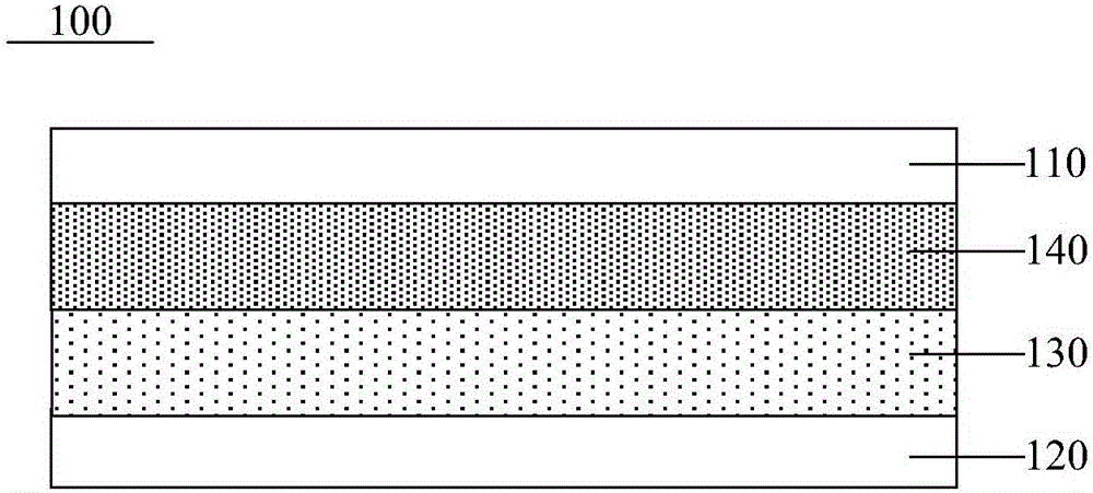
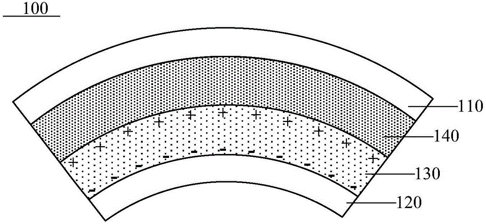
[0043] The embodiment of the present invention provides a pressure touch sensor 100, such as figure 1 As shown, it includes: a driving electrode 110, a sensing electrode 120, and a piezoelectric material layer 130 and a piezoresistive material layer 140 disposed therebetween.

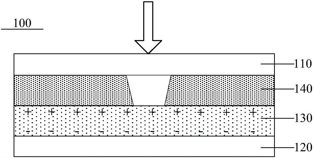
[0044] Here, the working principle of the pressure touch sensor 100 is:

[0045] In pressure sensing mode, such as figure 2 As shown, the upper and lower surfaces of...


PUM


Abstract

The invention provides a pressure touch sensor, a display device and a drive method for the same and relates to the technical field of display, wherein wrong recognition of pressure sensing can be prevented when the display device is bent. The pressure touch sensor comprises a drive electrode, a sensing electrode as well as a piezoelectric material layer and a piezo-resistance material layers disposed between the drive electrode and the sensing electrode.

Description

Technical field [0001] The invention relates to the field of display technology, in particular to a pressure touch sensor, a display device and a driving method thereof. Background technique [0002] With the development of information technology, the functions of mobile terminals are becoming more and more abundant, and the applications of various new technologies and new functions are also presented in different ways, and the pressure touch (3D-Touch) technology can sense the pressing force, Therefore, different functions can be realized based on different strengths and the user experience can be increased. [0003] Currently, pressure touch sensors based on the piezoelectric effect are generally used to implement multi-touch and pressure sensing functions. The pressure touch sensor includes a driving electrode and a sensing electrode, and a piezoelectric material layer located between the driving electrode and the sensing electrode; wherein the piezoelectric material layer is a...

Claims


Application Information

Patent Timeline
Patent Type & Authority Applications(China)
IPC IPC(8): G06F3/041
CPCG06F3/0414G06F3/0416G06F2203/04105G06F3/0412G06F3/04166G06F3/0445G06F3/0446H10N30/302H10K59/40H10K2102/311G06F2203/04104G06F2203/04102H10N30/853
Inventor 郭玉珍董学王海生吴俊纬刘英明许睿贾亚楠赵利军秦云科顾品超李昌峰丁小梁
Owner BOE TECH GRP CO LTD
Why Eureka
Try Eureka