Vision-based intelligent table top size detection method and system
A size detection and table top technology, applied in the field of image processing, can solve problems such as limited anti-interference ability, and achieve the effect of strong anti-interference ability
- Summary
- Abstract
- Description
- Claims
- Application Information
AI Technical Summary
Problems solved by technology
Method used
Image
Examples
Embodiment 1
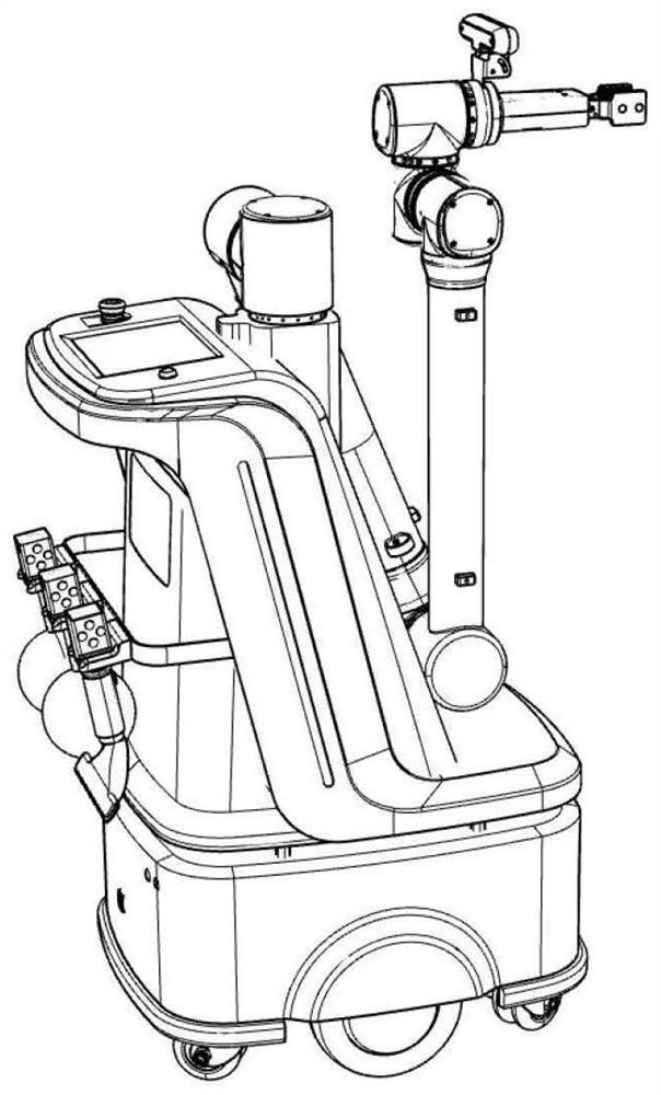
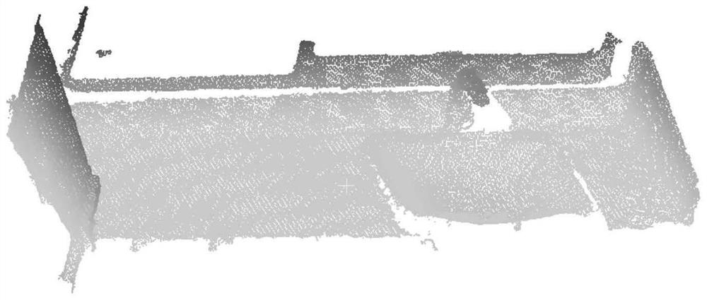
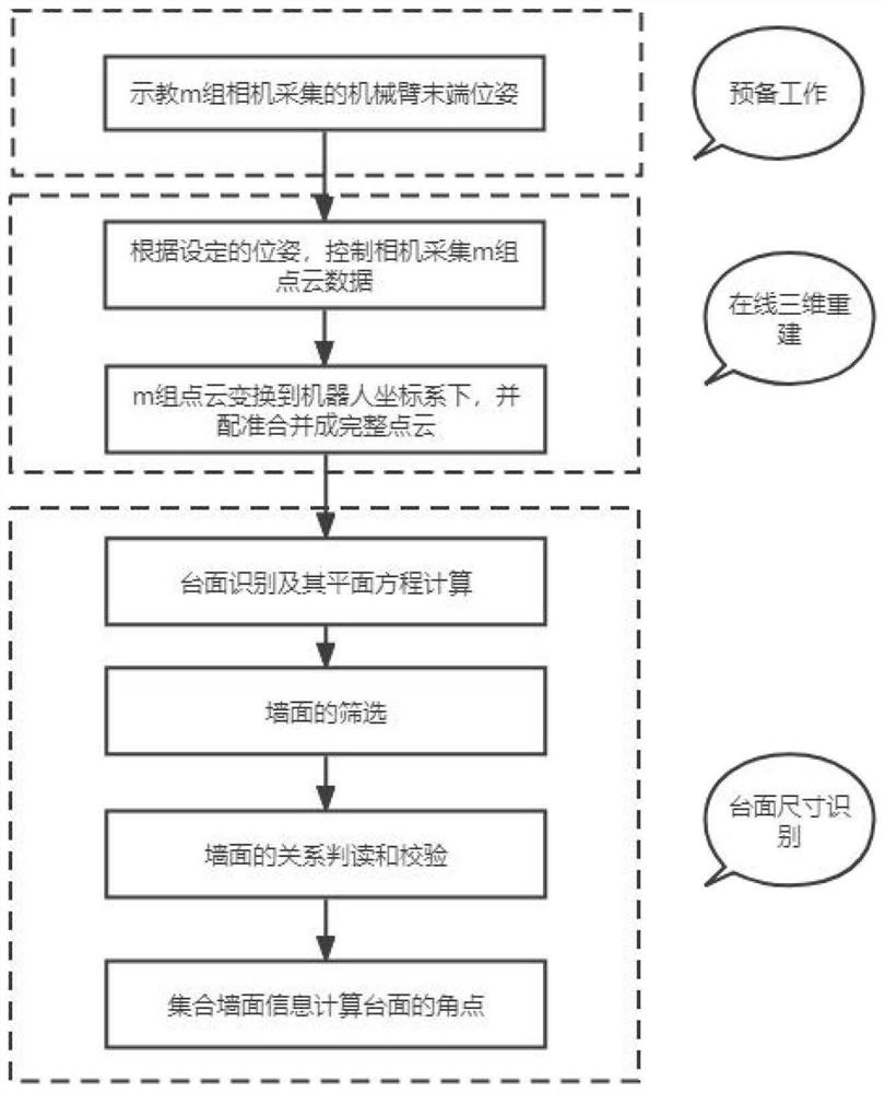
[0116] According to a visual-based intelligent table size detection method provided by the present invention, such as Figure 1-Figure 3 shown, including:
[0117] Step S1: collecting the pose of the robot's photographing point;
[0118] Specifically, in the step S1:
[0119] Teach the robot one or more camera points, navigate the robot to the robot working point in front of the table, make the Z-axis of the robot perpendicular to the ground, and the X-axis point to the front table, switch the robot to the teaching mode, and convert the real-time image captured by the camera Open;
[0120] Drag the end of the robotic arm of the robot to different poses, so that the cameras on the end of the robotic arm point to the preset positions respectively. According to the size of the table, select the number of poses m, and monitor the real-time image of the camera to ensure the adjacent poses. In this case, the image of the camera has overlapping areas above the preset value, and th...
Embodiment 2
[0167] Embodiment 2 is a preferred example of Embodiment 1, in order to describe the present invention in more detail.
[0168] Those skilled in the art can understand the method for detecting the size of a smart countertop based on vision provided by the present invention as a specific embodiment of the system for detecting the size of a smart countertop based on vision, that is, the system for detecting the size of the smart countertop based on vision. This can be achieved by executing the flow of steps of the method.
[0169] A system for visual-based intelligent countertop size detection provided according to the present invention includes:
[0170] Module M1: collect the pose of the robot's photographing point;
[0171] Specifically, in the module M1:
[0172] Teach the robot one or more camera points, navigate the robot to the robot working point in front of the table, make the Z-axis of the robot perpendicular to the ground, and the X-axis point to the front table, sw...
Embodiment 3
[0220] Embodiment 3 is a preferred example of Embodiment 1, in order to describe the present invention in more detail.
[0221] This system consists of a mobile chassis, a robotic arm, and a depth camera, such as figure 1 shown.
[0222] The method includes the following steps:
[0223] Step 1: Determine the pose of multiple camera points of the robot;
[0224] Step 2: Online 3D reconstruction of the countertop;
[0225] Step 3: Identify the corner points of the table based on the table model;
[0226] Wherein, step 1 includes the following steps:
[0227] Step 1.1: Teach the robot multiple camera points;
[0228] First, navigate the robot to the robot working point in front of the table. At this time, the Z-axis of the robot is perpendicular to the ground, and the X-axis points to the front table. And switch the robot to teaching mode, and open the real-time image captured by the camera at the same time.
[0229] Then drag the end of the robotic arm of the robot to dif...
PUM
 Abstract
Description
Claims
Application Information
 - R&D
- Intellectual Property
- Life Sciences
- Materials
- Tech Scout
- Unparalleled Data Quality
- Higher Quality Content
- 60% Fewer Hallucinations
Browse by: Latest US Patents, China's latest patents, Technical Efficacy Thesaurus, Application Domain, Technology Topic, Popular Technical Reports.
© 2025 PatSnap. All rights reserved.Legal|Privacy policy|Modern Slavery Act Transparency Statement|Sitemap|About US| Contact US: help@patsnap.com


