Plug-in type hydraulic and pneumatic integrated teaching experiment table control system

A control system and test bench technology, applied in the field of machinery, can solve the problems of backward control technology, unable to reflect hydraulic and pneumatic technology, etc.

Inactive Publication Date: 2017-06-09
何志杰
View PDF0 Cites 3 Cited by
  • Summary
  • Abstract
  • Description
  • Claims
  • Application Information

AI Technical Summary

Benefits of technology

This patented controller allows users who want learning how to program electronic devices like computers or robots with different types of controls from both relays and remote terminals through various techniques including Gas Liquide Technology (GLT) and Electrified Programmable Controlled Therapeutic Device (EPC).

Problems solved by technology

This patented technical problem addressed in the patents relates to developing an improved educational system for instructor learners who want to use these tools more easily during learning sessions without sacrificing accuracy.

Method used


Image

  • Plug-in type hydraulic and pneumatic integrated teaching experiment table control system
  • Plug-in type hydraulic and pneumatic integrated teaching experiment table control system

Examples


Embodiment Construction

[0014] The present invention will be further described below in conjunction with drawings and embodiments.

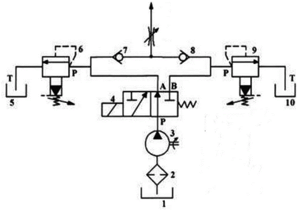
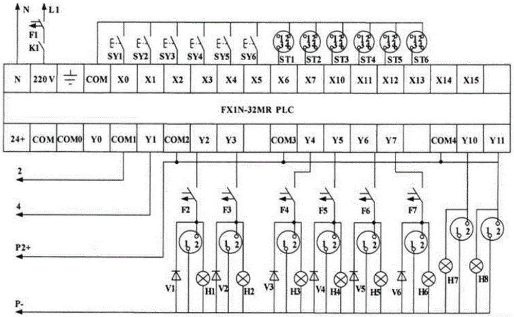
[0015] Such as figure 1 , The control system of the test bench includes two parts: the hydraulic source pressure control and the electrical control, and the electrical control is divided into two parts: the strong current control system and the weak current control system. Considering the compact structure and the separation of strong and weak electricity, the hydraulic source pressure control part and the strong electric control part are placed on the lower part of the experimental platform, and the weak current control part is placed on the upper part of the console.

[0016] The hydraulic source pressure control system is equipped with a flow control valve, which can adjust the required flow according to requirements. A quantitative vane pump 3 is used to supply oil to the system, and two kinds of system maximum pressures can be obtained through the reversing cabine...


PUM


Abstract

A plug-in hydraulic and pneumatic comprehensive teaching experiment platform control system includes two parts: hydraulic source pressure control and electrical control, wherein the electrical control is divided into two parts: a strong current control system and a weak current control system. The relay control mode and PLC control mode provided by the control system enable students to learn PLC programming control in addition to mastering traditional relay control, and have the experimental ability of PLC control and computer communication and online testing. It integrates gas-hydraulic technology and electrical PLC control technology, and is suitable for professional training assessments such as electrician and mechatronics.

Description


Claims


Application Information

Patent Timeline
Owner 何志杰
Why Eureka
Try Eureka