Sowing equipment used for farming

A technology of equipment and seeding mechanism, applied in sowing, hole seeding, application and other directions, can solve the problem of high cost, achieve the effect of saving seeds, ingenious structure and improving economic benefits

Pending Publication Date: 2017-06-13
湖南天爱农业科技有限公司
View PDF0 Cites 15 Cited by
  • Summary
  • Abstract
  • Description
  • Claims
  • Application Information

AI Technical Summary

Problems solved by technology

In agricultural cultivation, sowing is a very important link. However, the cost of large-scale seeders on the market is often too high, and ordinary agricultural families cannot afford them. Even if they are rented, the rent is a fortune for ordinary families. small expenses

Method used


Image

  • Sowing equipment used for farming
  • Sowing equipment used for farming
  • Sowing equipment used for farming

Examples


Embodiment 1

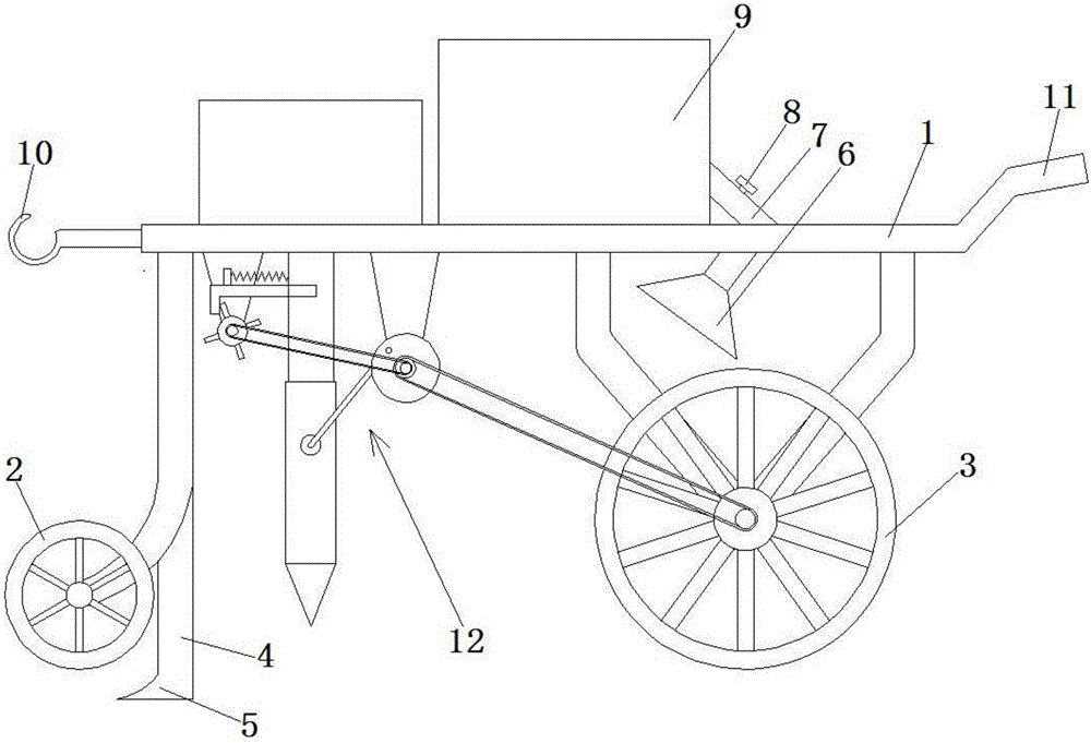
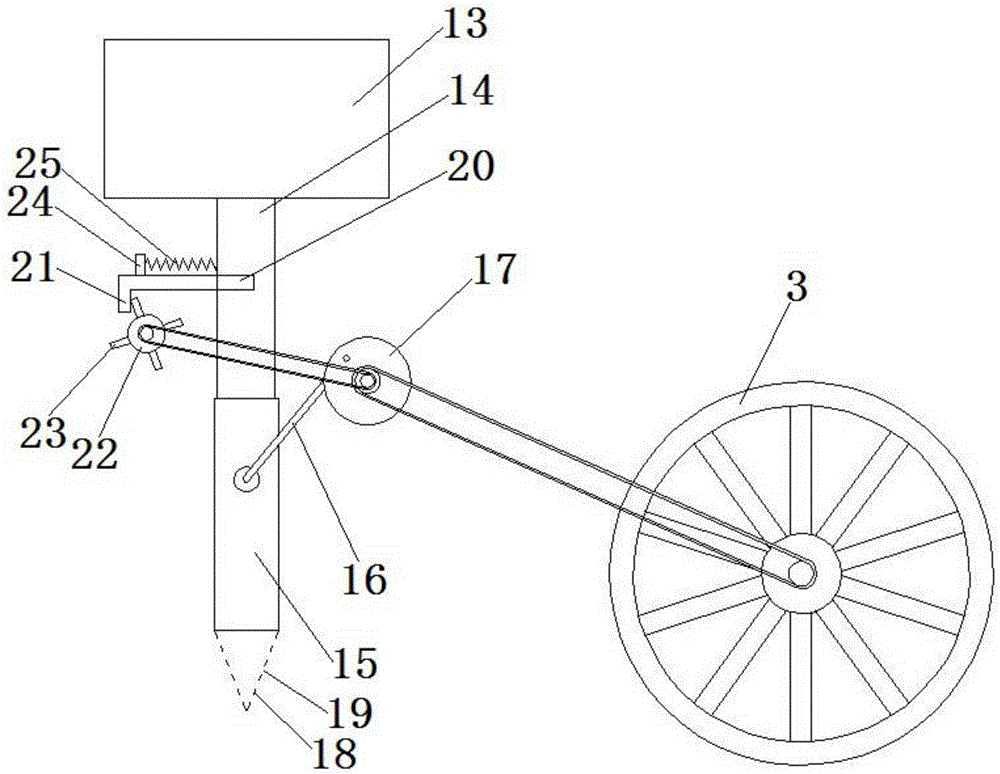
[0021] see Figure 1-2 , a kind of equipment used for sowing during farming, including a frame 1, and a sowing mechanism 12 arranged on the frame 1, two front wheels 2 and two rear wheels are provided at the front and rear of the frame 1 3. Described sowing mechanism 12 comprises seed box 13 and seed outlet pipe, and described seed outlet pipe includes upper pipe 14 and lower pipe 15 that are nested with each other, and described upper pipe 14 is connected with seed box 13; Described frame 1 bottom is provided with A first rotating disk 17 is arranged, and the first rotating disk 17 is connected with the rear wheel 3 axle drive by a belt. When the rear wheel 3 rotates, it drives the first rotating disk 17 to rotate, and the first rotating disk 17 drives the lower tube 15 through the connecting rod 16 to move up and down. In practical application, the staff pushes the frame 1 forward, and the lower tube 15 pokes into the soil when it moves downward, and the seeds pass through...

Embodiment 2

[0026] The bottom of the lower tube 15 is provided with a conical head 18 which is hollow inside and communicated with the lower tube 15 . The outer surface of the conical head 18 is provided with a number of seed outlet holes 19 . The design of the cone head 18 at the bottom of the down tube 15 can make the down tube 15 poke into the soil more easily, and the seeds leak out from the seed hole 19.

Embodiment 3

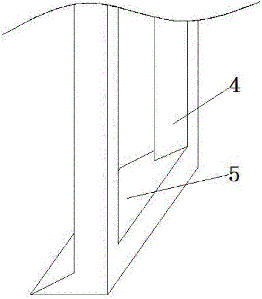
[0028] see image 3 A soil loosening mechanism is also provided below the frame 1, and the soil loosening mechanism includes two pillars 4 vertically arranged at the bottom of the frame 1, and a blade 5 is connected to the bottom of the two pillars 4, and the blade 5 is located at the bottom of the frame 1. The front part of the pipe 15, and the position of the blade 5 is lower than the lowest point of the wheel. When the staff promotes the frame 1 to advance, the spatula 5 scoops up the soil earlier to achieve the purpose of loosening the soil, so that the down pipe 15 at the rear is conveniently poked into the soil.


PUM


Abstract

The invention discloses a device for sowing during farming, which includes a frame and a sowing mechanism arranged on the frame. Two front wheels and two rear wheels are arranged at the front and rear of the frame. The sowing mechanism includes The seed box and the seed delivery tube, the seed delivery tube includes an upper tube and a lower tube that are nested with each other, and the upper tube is connected to the seed box; the bottom of the frame is provided with a first turntable, and the first turntable is connected to the rear wheel shaft through a belt. The edge of a turntable is hinged with a connecting rod, and the other end of the connecting rod is hinged with the outer wall of the lower tube; there is a flat opening on one side of the upper tube, and a baffle is inserted in the opening, and the end of the baffle is exposed outside the upper tube. The end located outside the upper tube is provided with a bending part; the bottom of the frame is provided with a second turntable, the second turntable is located next to the bending part, and the outer surface of the second turntable is provided with several convex lines, and the raised lines The bending part can be moved; the retainer is provided with a fixed block, the fixed block is connected with a spring, and the other end of the spring is connected with the outer wall of the upper tube.

Description

technical field [0001] The invention relates to the field of agricultural production, in particular to a device for sowing seeds during farming. Background technique [0002] With the development of science and technology, agricultural planting is becoming more and more mechanized, and the traditional use of manpower for agricultural farming has become a thing of the past. In agricultural cultivation, sowing is a very important link. However, the cost of large-scale seeders on the market is often too high, and ordinary agricultural families cannot afford them. Even if they are rented, the rent is a fortune for ordinary families. small expenses. [0003] In view of this need, the present invention proposes a sowing mechanism with a smaller volume and lower cost under the premise of ensuring the sowing effect. Contents of the invention [0004] In order to achieve the above object, the present invention provides the following technical solutions: a device for sowing during...

Claims


Application Information

Patent Timeline
Patent Type & Authority Applications(China)
IPC IPC(8): A01C7/00A01C5/04
CPCA01C7/002A01C5/04
Inventor 刘成生李媛妹佘芳
Owner 湖南天爱农业科技有限公司
Why Eureka
Try Eureka