Flushing pipe and flushing equipment

A technology for flushing tubes and equipment, used in enema/irrigator, medical science, surgery, etc., can solve problems such as difficulty and achieve sufficient flushing effect

Pending Publication Date: 2017-06-13
曾娟
View PDF0 Cites 1 Cited by
  • Summary
  • Abstract
  • Description
  • Claims
  • Application Information

AI Technical Summary

Problems solved by technology

In the process of realizing the invention, the inventor found that the flushing tube in the prior art has the following disadvantages: the liquid can only be sprayed in one direction after passing through the liquid outlet 1311, so after the flushing tube 130 is inserted into the human organ, the When human organs are attached to the outer surface of the flushing tube 130, it is difficult for the liquid sprayed from the liquid outlet 1311 to reach around the liquid outlet 131 to fully clean the affected area

Method used


Image

  • Flushing pipe and flushing equipment
  • Flushing pipe and flushing equipment
  • Flushing pipe and flushing equipment

Examples


specific Embodiment 1

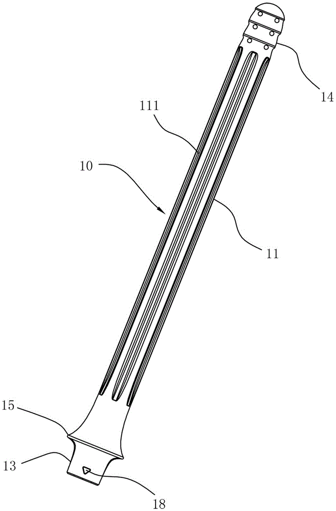
[0029] Such as image 3 As shown, it is a structural view of a preferred embodiment of the flushing pipe in the present invention. The flushing tube 10 disclosed in this preferred embodiment is intended to be connected to a flushing device 20 (refer to Figure 6 shown) to deliver the fluid to the designated location, such as the affected area to be rinsed.

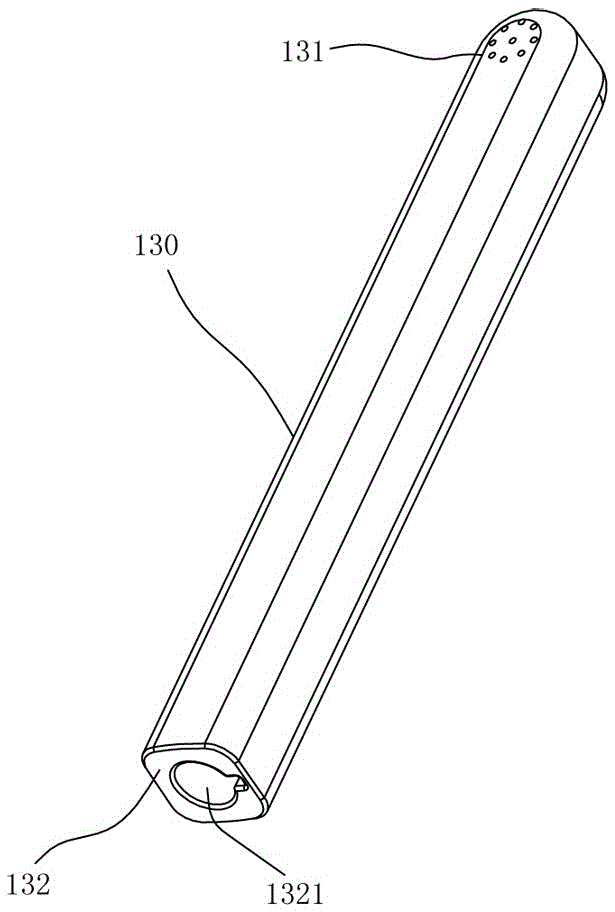
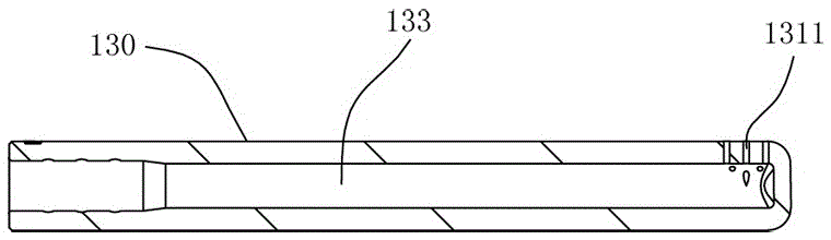
[0030] Such as image 3 , Figure 4 , Figure 5 As shown, the flushing tube 10 includes a tube body 11 and a liquid channel 12 disposed in the tube body 11 , wherein the outer surface of the tube body 11 is configured as a circle. The tube body 11 includes a connecting end 13 and a liquid outlet 14 , the connecting end 13 is provided with a liquid inlet 17 communicating with the liquid channel 12 , and the connecting end 13 is used for connecting with an external flushing device 20 . In this embodiment, the pipe wall of the liquid outlet 14 is provided with 12 liquid injection ports 141 communicating with the liquid c...

specific Embodiment 2

[0039] Such as Figure 6 As shown, it is a structural view of a preferred embodiment of the flushing device with the flushing pipe in the present invention. The flushing device 20 includes a main body 21 , a liquid storage tank 22 and a flushing pipe 10 , and the main body 21 is connected to the liquid storage tank 22 and the flushing pipe 10 respectively. Such as Figure 7 As shown, the main body 21 is provided with a control circuit 211, a pump 212, a heating element 213, a power supply 214 and a temperature sensor 215. The pump 211, the heating element 213, the power supply 214 and the temperature sensor 215 are all electrically connected to the control circuit 211. The pump 211 is adapted to suck the liquid in the liquid storage tank 22 to the flushing pipe 10 and flow out from the liquid spray port 141 .

[0040] In this embodiment, the heating element 213 itself is used for both heating and detecting its own temperature, the heating element 213 is used for heating the ...


PUM


Abstract

The invention discloses a flushing pipe capable of allowing liquid to flow to periphery of a lateral surface of a liquid output end, and flushing equipment. The flushing pipe is used for being connected with the flushing equipment to transport the liquid to a specified position, and comprises a pipe body and a liquid channel arranged in the pipe body, wherein the pipe body comprises a connection end and the liquid output end, the connection end is provided with a liquid inlet communicating with the liquid channel, the liquid output end is provided with at least one liquid spraying hole communicating with the liquid channel, at least one liquid guide groove is also arranged on the lateral surface of the liquid output end, the at least one liquid spraying hole is arranged in the at least one liquid guide groove, and the liquid guide groove guides the liquid flowing out from the liquid spraying hole arranged therein to flow to the periphery of the lateral surface of the liquid output end.

Description

technical field [0001] The invention relates to the field of medical equipment, in particular to a washing tube and washing equipment suitable for washing women's vaginas or cleaning the anus and intestines of human bodies. Background technique [0002] The irrigators sold on the market are mainly used in the gynecological clinical treatment process, and the irrigators generally include a host and a rinsing tube. When the patient needs to rinse or treat the vagina or anorectum, the irrigation tube can be inserted into the affected area, and then the main unit can be started to spray water or medicinal liquid to rinse the affected area, so as to achieve the purpose of cleaning or treatment. [0003] Flushing pipe in the prior art can refer to figure 1 and figure 2 As shown, the flushing pipe 130 includes a liquid outlet 131 , a connection end 132 and a liquid outlet channel 133 , the connection end 132 is provided with a liquid inlet 1321 , and the liquid outlet 131 is con...

Claims


Application Information

Patent Timeline
IPC IPC(8): A61M3/02A61M31/00
CPCA61M3/02A61M3/0279A61M31/00A61M2205/3368A61M2210/1064A61M2210/1067A61M2210/1475
Inventor 李锦添曾娟
Owner 曾娟
Why Eureka
Try Eureka