Smoke extraction and dust removal equipment
A technology for dust removal equipment and oil fume, which is applied in the directions of removing smoke and dust, cleaning methods and utensils, chemical instruments and methods, etc., can solve the problems of difficult cleaning, blade pollution, etc., and achieves the effect of convenient manufacturing, installation and maintenance, and simple structure.
- Summary
- Abstract
- Description
- Claims
- Application Information
AI Technical Summary
Problems solved by technology
Method used
Image

Examples
example 1
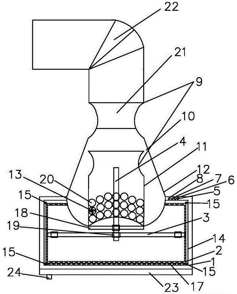
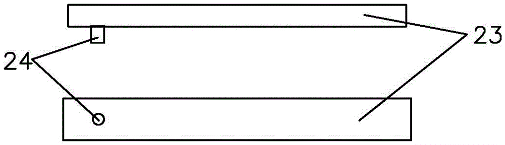
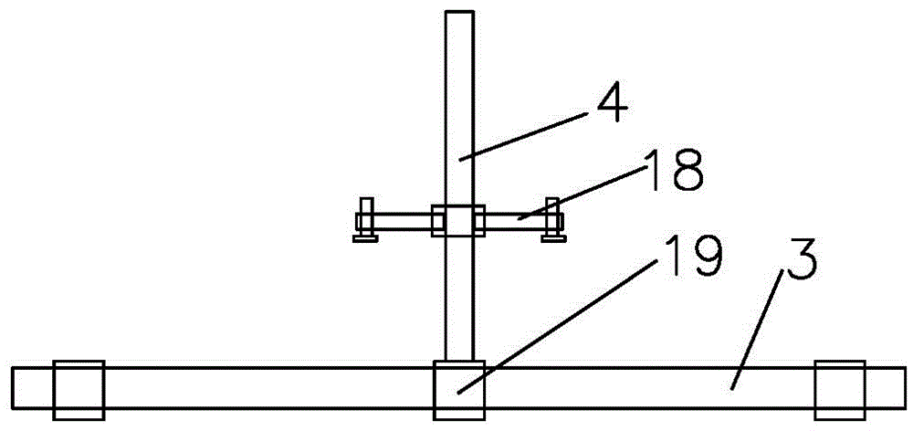
[0035]A smoke extraction and dust removal equipment, which is realized in this way: an air collection chamber, an inner air duct body, an air extraction port at the lower part of the inner air duct body, an outlet formed by the upper part of the inner air duct body and a pressurized chamber, and an exhaust air connected to the upper part of the pressurized chamber The specific structure of the channel and the interface with the outer air pipe on the upper part of the exhaust duct is: smoke and dust collector housing 1, the inner edge of which is fixedly connected with a fluid guide cover by screws (the guide vanes in the guide cover are arranged clockwise in the northern hemisphere , the southern hemisphere is arranged counterclockwise) 2, the outside of the shroud 2 is covered with an oil filter 17, and there is a horizontal ultraviolet lamp 3 fixedly connected to the inner wall of the chamber by screws in the chamber of the smoke and dust collector housing 1, and the middle pa...
example 2
[0037] A kind of smoke extraction and dust removal equipment, the smoke and dust collector housing 1, the inner edge of which is fixedly connected with a fluid guide cover by screws (the guide vanes in the guide cover are arranged clockwise in the northern hemisphere and counterclockwise in the southern hemisphere) 2, the guide The outside of the flow cover 2 is covered with an oil filter 17. There is a horizontal ultraviolet lamp 3 fixedly connected to the inner wall of the chamber by screws in the cavity of the smoke and dust collector housing 1. The middle part of the horizontal ultraviolet lamp 3 has a connecting clip 19 for the ultraviolet lamp. The upper center of the housing 1 has a pressurized air cavity body 12 fixedly connected with the inner cavity body by screws, and the lower inner opening of the pressurized air cavity body 12 is fixedly connected with an inner air duct body 11 by screws, and the inner air duct body 11 is equipped with a There are annular mesh air ...
example 3
[0039] A kind of smoke extraction and dust removal equipment, the smoke and dust collector housing 1, the inner edge of which is fixedly connected with a fluid guide cover by screws (the guide vanes in the guide cover are arranged clockwise in the northern hemisphere and counterclockwise in the southern hemisphere) 2, the guide The outside of the flow cover 2 is covered with an oil filter 17. There is a horizontal ultraviolet lamp 3 fixedly connected to the inner wall of the chamber by screws in the cavity of the smoke and dust collector housing 1. The middle part of the horizontal ultraviolet lamp 3 has a connecting clip 19 for the ultraviolet lamp. The upper center of the housing 1 has a pressurized air cavity body 12 fixedly connected with the inner cavity body by screws, and the lower inner opening of the pressurized air cavity body 12 is fixedly connected with an inner air duct body 11 by screws, and the inner air duct body 11 is equipped with a There are two 180-degree sy...
PUM
 Abstract
Description
Claims
Application Information
 - R&D
- Intellectual Property
- Life Sciences
- Materials
- Tech Scout
- Unparalleled Data Quality
- Higher Quality Content
- 60% Fewer Hallucinations
Browse by: Latest US Patents, China's latest patents, Technical Efficacy Thesaurus, Application Domain, Technology Topic, Popular Technical Reports.
© 2025 PatSnap. All rights reserved.Legal|Privacy policy|Modern Slavery Act Transparency Statement|Sitemap|About US| Contact US: help@patsnap.com