
Self-regulating ventilation device and locomotive for high-speed rail transit

A high-speed track and ventilation device technology, applied to locomotives and other directions, can solve the problems of no air intake, low air intake of ventilators, and affecting the work of locomotives

Active Publication Date: 2019-08-20
ZHUZHOU ELECTRIC LOCOMOTIVE CO LTD
View PDF5 Cites 0 Cited by
  • Summary
  • Abstract
  • Description
  • Claims
  • Application Information

AI Technical Summary

Problems solved by technology

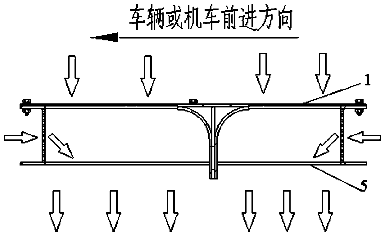
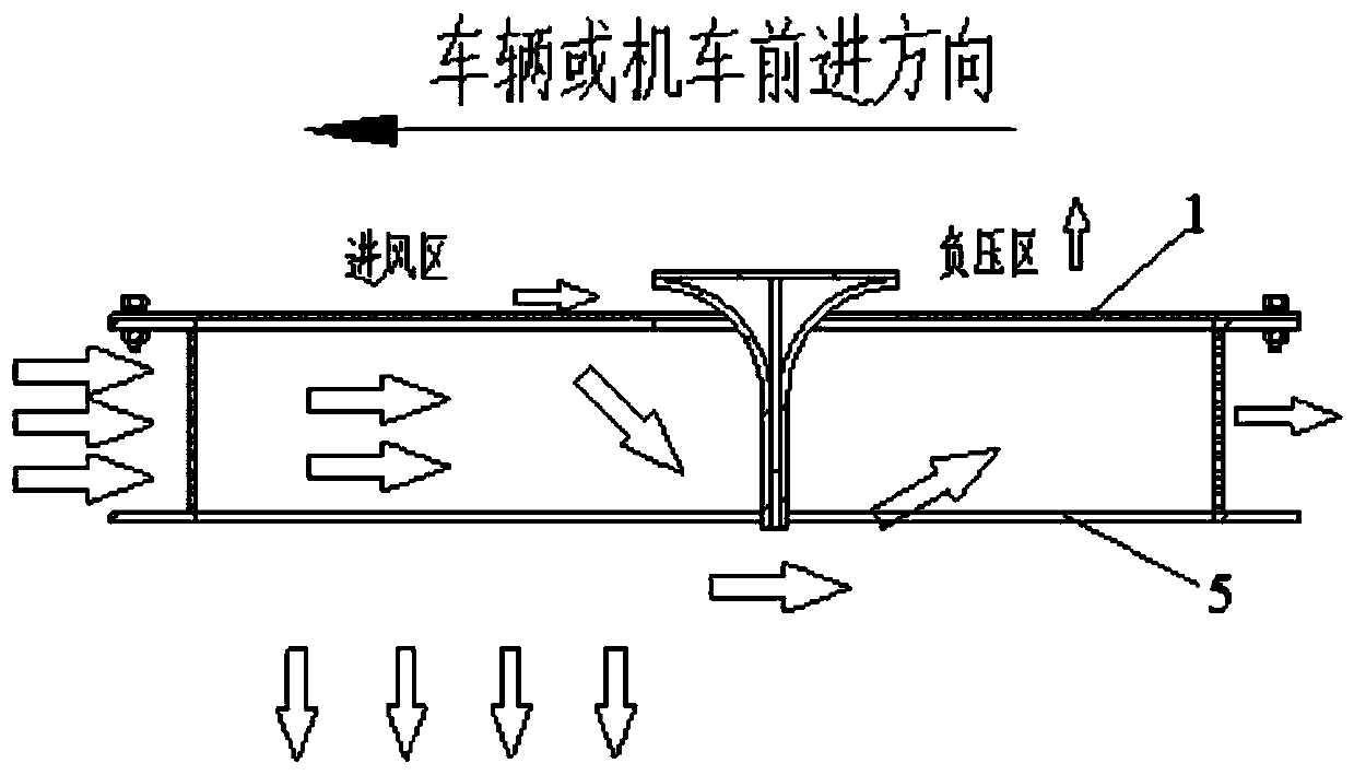
[0002] At present, the domestic high-speed vehicle or locomotive ventilator air intake filter is installed on the surface of the vehicle or locomotive. When the vehicle or locomotive is running at high speed, the air intake surface at the ventilation device is in a negative pressure area. Under the action of the same ventilator, the higher the speed , the greater the negative pressure effect of the air inlet surface at the ventilation device, the lower or even no air intake of the fan will affect the work of the ventilation and cooling components in the locomotive

Method used


Image

  • Self-regulating ventilation device and locomotive for high-speed rail transit
  • Self-regulating ventilation device and locomotive for high-speed rail transit
  • Self-regulating ventilation device and locomotive for high-speed rail transit

Examples


Embodiment Construction

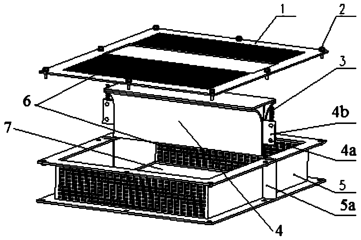
[0015] Such as figure 1 As shown, an embodiment of the present invention includes a cylinder body 5 with an open end; the open end of the cylinder body 5 is covered by a cover plate 1 (the cover plate 1 and the cylinder body 5 are fixedly connected by a fastener 2), and the cylinder body The body 5 and the cover 1 form an installation space 7; the two opposite sides, the bottom, and the cover 1 of the cylinder 5 are provided with a plurality of air inlets 6.

[0016] Such as figure 1 and Figure 4 As shown, the spoiler 4 includes a horizontal portion 41; both sides of the horizontal portion 41 are connected to a vertical portion 43 through a connecting portion 42 for changing the wind direction. The two sides of the cylinder 5 opposite to the air inlet are provided with a card slot 5a (the card slot 5a protrudes outward); both sides of the vertical part 42 are provided with a mounting plate 4b; the two mounting plates 4b are respectively embedded Balls 4a are mounted on the...


PUM


Abstract

The invention discloses a self-adjustment ventilation device for high-speed rail transit and a locomotive. The self-adjustment ventilation device comprises a barrel with one open end. The open end of the barrel is covered with a cover plate, and the barrel and the cover plate form an installation space. The two opposite side edges of the barrel and the cover plate are all provided with a plurality of air inlets. A spoiler capable of moving in the vertical direction in the installation space is installed in the barrel. Through the self-adjustment ventilation device for the high-speed rail transit and the locomotive, the problems that air cannot enter the ventilation device or little air enters the ventilation device due to negative pressure generated near the surface of a vehicle body during traveling of a high-speed vehicle or the locomotive are solved, and effective air inlet quantity of the ventilation device can be adjusted automatically according to the operation speed of the vehicle or the locomotive.

Description

technical field [0001] The invention relates to the technical field of rail transit locomotives, in particular to a self-regulating ventilation device for high-speed rail transit and a locomotive. Background technique [0002] At present, the domestic high-speed vehicle or locomotive ventilator air intake filter is installed on the surface of the vehicle or locomotive. When the vehicle or locomotive is running at high speed, the air intake surface at the ventilation device is in a negative pressure area. Under the action of the same ventilator, the higher the speed , the greater the negative pressure effect of the air inlet surface at the ventilation device, the lower the air intake of the fan or even no air intake, which will affect the work of the ventilator cooling components in the locomotive. Contents of the invention [0003] The technical problem to be solved by the present invention is to provide a self-regulating ventilation device and a locomotive for high-speed ...

Claims


Application Information

Patent Timeline
Patent Type & Authority Patents(China)
IPC IPC(8): B61C17/04
Inventor 廖章庆朱茂华陈露李时民李仕林徐力
Owner ZHUZHOU ELECTRIC LOCOMOTIVE CO LTD
Learn More