Household lighting bulb placing box

A technology for placing boxes and light bulbs, applied in the field of placing boxes, can solve the problems of inconvenient placement and easy damage of light bulbs

Active Publication Date: 2017-06-13
安徽翰邦科技咨询有限公司
View PDF7 Cites 4 Cited by
  • Summary
  • Abstract
  • Description
  • Claims
  • Application Information

AI Technical Summary

Problems solved by technology

[0005] In order to overcome the shortcomings of inconvenient and easily damaged bulbs in the present invention, the technical problem to be solved by the present invention is to provide a household lighting bulb storage box that is convenient to place and not easily damaged.

Method used


Image

  • Household lighting bulb placing box
  • Household lighting bulb placing box
  • Household lighting bulb placing box

Examples


Embodiment 1

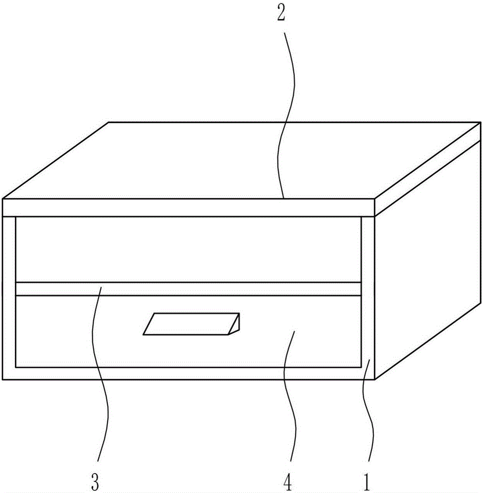
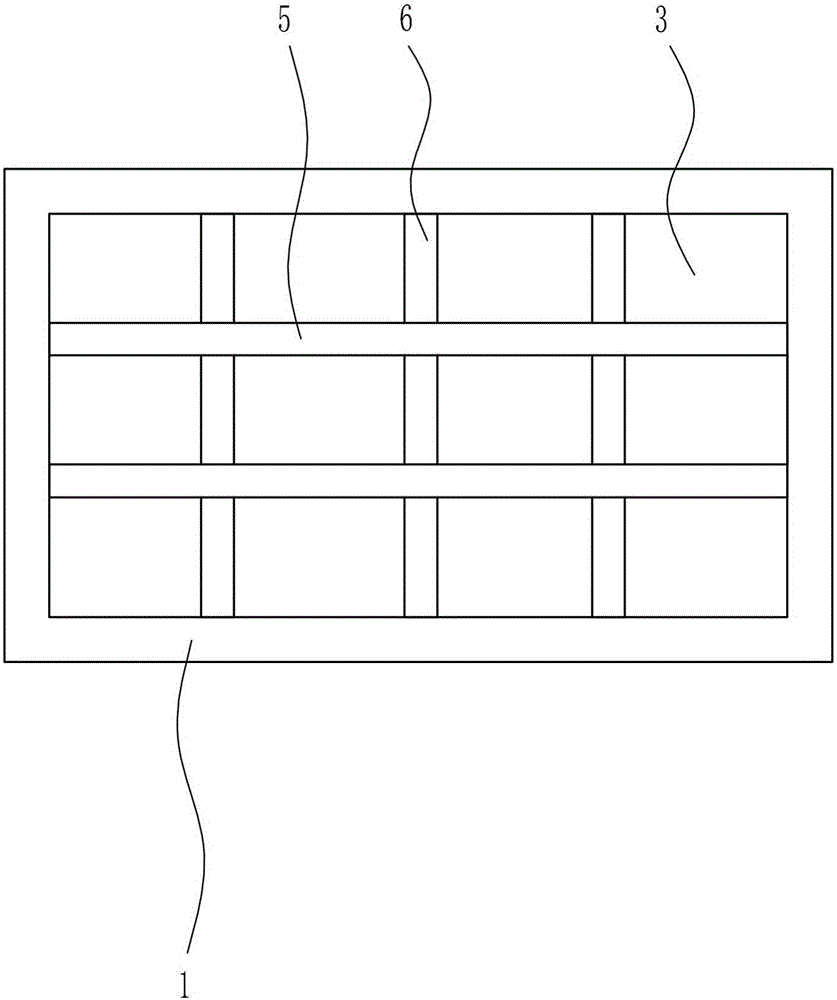
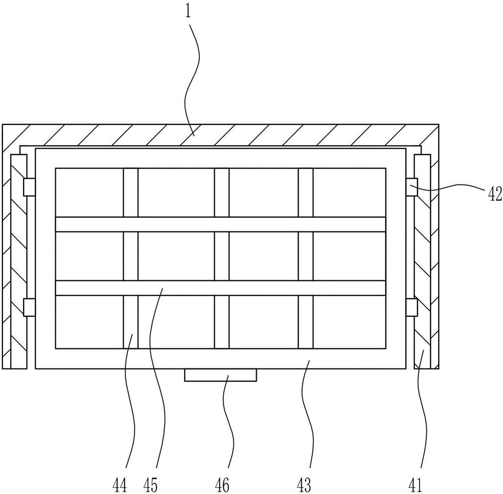
[0029] A kind of household light bulb placement box, such as Figure 1-6 As shown, it includes a box body 1, a cover plate 2, an isolation plate 3, a lower placement device 4, a third partition plate 5 and a fourth partition plate 6, the top of the box body 1 is rotatably connected with the cover plate 2, and the box body 1 An isolation plate 3 is provided at the center of the front side, and a lower placement device 4 is provided between the bottom of the isolation plate 3 and the inner bottom of the box body 1, and a third partition is evenly provided between the left and right walls of the box body 1 on the isolation plate 3 Plate 5, the fourth dividing plate 6 is evenly arranged between the front and rear walls of the box body 1 on the insulating plate 3, and the third dividing plate 5 and the fourth dividing plate 6 connect the top of the insulating plate 3 and the bottom of the cover plate 2 The space in between is divided into twelve equal parts.

Embodiment 2

[0031] A kind of household light bulb placement box, such as Figure 1-6 As shown, it includes a box body 1, a cover plate 2, an isolation plate 3, a lower placement device 4, a third partition plate 5 and a fourth partition plate 6, the top of the box body 1 is rotatably connected with the cover plate 2, and the box body 1 An isolation plate 3 is provided at the center of the front side, and a lower placement device 4 is provided between the bottom of the isolation plate 3 and the inner bottom of the box body 1, and a third partition is evenly provided between the left and right walls of the box body 1 on the isolation plate 3 Plate 5, the fourth dividing plate 6 is evenly arranged between the front and rear walls of the box body 1 on the insulating plate 3, and the third dividing plate 5 and the fourth dividing plate 6 connect the top of the insulating plate 3 and the bottom of the cover plate 2 The space in between is divided into twelve equal parts.

[0032] Bottom placin...

Embodiment 3

[0034] A kind of household light bulb placement box, such as Figure 1-6 As shown, it includes a box body 1, a cover plate 2, an isolation plate 3, a lower placement device 4, a third partition plate 5 and a fourth partition plate 6, the top of the box body 1 is rotatably connected with the cover plate 2, and the box body 1 An isolation plate 3 is provided at the center of the front side, and a lower placement device 4 is provided between the bottom of the isolation plate 3 and the inner bottom of the box body 1, and a third partition is evenly provided between the left and right walls of the box body 1 on the isolation plate 3 Plate 5, the fourth dividing plate 6 is evenly arranged between the front and rear walls of the box body 1 on the insulating plate 3, and the third dividing plate 5 and the fourth dividing plate 6 connect the top of the insulating plate 3 and the bottom of the cover plate 2 The space in between is divided into twelve equal parts.

[0035]Bottom placing...


PUM


Abstract

The invention relates to placing boxes, in particular to a household lighting bulb placing box. The household lighting bulb placing box comprises a box body and the like and is characterized in that a cover plate is rotatably connected to the top of the box body, a partition is arranged at the center of the front side of the box body, a lower placing device is arranged between the bottom of the partition and the inner bottom of the box body, third separation plates are evenly arranged on the partition and between the left wall and the right wall in the box body, and fourth separation plates are evenly arranged on the partition and between the front wall and the rear wall in the box body. The household lighting bulb placing box has the advantages that the box is convenient in bulb placing and less prone to damage, the separation plates made of sponges are arranged in the box body to evenly separate the box body into multiple small spaces, and spare bulbs placed in the small spaces can be fixed in the small spaces and are less prone to rolling.

Description

technical field [0001] The invention relates to a placement box, in particular to a placement box for household lighting bulbs. Background technique [0002] The light bulb, a lighting source that emits light and heat through electrical energy, was invented by Henri Goebbels. "Lighting appliances" are produced with the continuous development of human civilization. The most common function of light bulbs is lighting. With the development of society, the use of light bulbs has also undergone different changes. At first, it may be for the convenience of production and life, but with the progress of society, there have been obvious changes in the use of light bulbs. Functional lamps for different purposes such as "environment, decoration" and so on. The light bulb is mainly composed of several parts such as a filament, a glass shell, and a lamp holder. The metal material in the bulb is a conductor, while the glass shell and the plastic part of the lamp cap are insulators. I...

Claims


Application Information

Patent Timeline
IPC IPC(8): B65D25/04B65D25/24B65D55/10
CPCB65D25/04B65D25/24B65D55/10
Inventor 张晓艳
Owner 安徽翰邦科技咨询有限公司
Why Eureka
Try Eureka