Pneumatic temporary support device for fully mechanized excavation

A temporary support and full-mechanized excavation technology, which is applied in mine roof support, mining equipment, earthwork drilling and mining, etc., can solve the problems of increasing wear of connecting rods and hinged shafts, increasing support work procedures, and poor applicability, etc. Achieve the effect of avoiding potential safety hazards and saving support work procedures

Active Publication Date: 2019-10-25
北京双泰气动设备有限公司 +2
View PDF6 Cites 0 Cited by
  • Summary
  • Abstract
  • Description
  • Claims
  • Application Information

AI Technical Summary

Problems solved by technology

Although this device does not occupy the ground space during transportation, when the support device is working, the support device needs to be removed from the pneumatic traction device, placed on the ground, and finally unfolded into a support umbrella layer by layer to complete the support action , In addition, it must be reinstalled on the traction device after being stowed away, which increases the process of support work, and in fact cannot achieve the real integration of transportation and support
And its supporting device includes a link mechanism composed of multi-section connecting rods. These link mechanisms include multiple hinge points. Wear between the rod and the hinge shaft reduces the stability of the support device in use
In addition, because there are too many linkage mechanisms, factors such as the degree of freedom of rotation need to be considered in the design, so the size of the support device and the proportion of each component will be more restricted, resulting in poor applicability

Method used


Image

  • Pneumatic temporary support device for fully mechanized excavation
  • Pneumatic temporary support device for fully mechanized excavation
  • Pneumatic temporary support device for fully mechanized excavation

Examples


Embodiment Construction

[0036] In order to enable those skilled in the art to better understand the solution of the present invention, the present invention will be further described in detail below in conjunction with the accompanying drawings and specific embodiments.

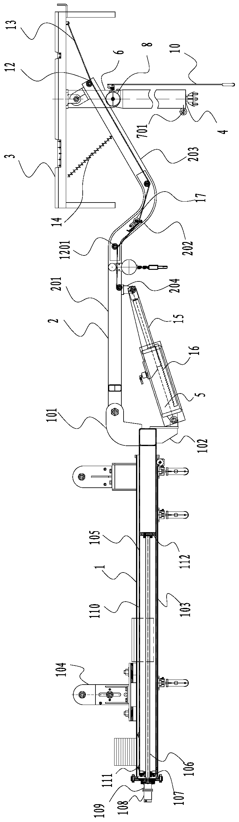
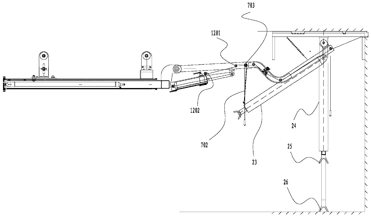
[0037] Such as Figure 1-10 As shown, the pneumatic temporary support device for fully mechanized excavation includes an underframe 1 , a cantilever 2 and a support platform 3 . One end of the cantilever 2 is connected to the chassis 1, and the other end is connected to the supporting platform 3. During work, the underframe 1 is assembled on a track 27 located at the upper part of the roadway, and the traveling device drives the pneumatic temporary support device for fully mechanized excavation to move. The pneumatic temporary support device for fully mechanized excavation also includes a first support cylinder 4 connected to the lower end of the support platform 3 as a support between the support platform 3 and the ground. A seco...


PUM


Abstract

The invention discloses a pneumatic temporary support device for fully-mechanized excavating. The pneumatic temporary support device comprises a support platform, a cantilever and a bottom rack used for being hung on a rail, wherein one end of the cantilever is hinged to the bottom rack, and the other end of the cantilever is connected to the support platform; a first support air cylinder is connected to the lower portion of the support platform, and the push rod of the first support air cylinder extends out downwardly to support the ground; one end of the cylinder barrel of a second support air cylinder is hinged to the bottom rack, and the push rod of the second support air cylinder is hinged to the lower portion of the cantilever. The pneumatic temporary support device has the advantages that the support device can be hung on the rail and moved to an appointed support operation position to perform support operation, and the support device is unaffected by tunnel terrain.

Description

technical field [0001] The invention relates to roadway support equipment, in particular to a pneumatic temporary support device for fully mechanized excavation. Background technique [0002] At present, comprehensive mechanized excavation methods are commonly used in coal mine underground roadways. During fully mechanized excavation, support devices are usually installed on the roadheader. For example, Chinese patent CN104500086A discloses a roadway unmanned and bolt-digging integrated machine, and its supporting system is driven by the crawler belt of the roadheader to move on the ground of the roadway. This support system that walks on the ground is easily affected by the ground terrain of the roadway, and the balance of the support system is poor when it works. In addition, during the movement of the ground, a large roadway space is occupied, and if other equipment or other workers are installed in the roadway space, the transportation of the support system will be hin...

Claims


Application Information

Patent Timeline
Patent Type & Authority Patents(China)
IPC IPC(8): E21D23/04E21D23/16
CPCE21D23/04E21D23/0409E21D23/16
Inventor 周文川谢强珍何雨生白麦营胡兰田张全明李振李浩
Owner 北京双泰气动设备有限公司
Why Eureka
Try Eureka