Device for detecting rigidity of gyration reduction gear

A technology of a rotary reducer and a detection device, which is applied to the measurement device, the test of mechanical parts, the test of machine/structural parts, etc., can solve the problems of low reliability of test results, low test efficiency, and inability to meet the needs of industrial production and use, etc. Achieve a high degree of automation, improve installation efficiency, and ensure the effect of installation accuracy

Active Publication Date: 2017-06-13
ZHEJIANG SUPCON SOLAR TECHNOLOGY CO LTD
View PDF6 Cites 1 Cited by
  • Summary
  • Abstract
  • Description
  • Claims
  • Application Information

AI Technical Summary

Problems solved by technology

[0002] As a commonly used transmission component, the rotary reducer is widely used in many technical fields, but before applying the reducer, it is necessary to check whether the performance of the reducer meets the requirements in all aspects. Among them, during the application process of the rotary reducer, its There will be a load on it, and the rotary reducer drives the load to rotate. In order for the rotary reducer to drive the load to run smoothly, the reducer is required to have high torsional rigidity. At the same time, the load on the reducer may exert a certain amount of overturning on the reducer. In this respect, the reducer is required to have high bending rigidity. In view of the above problems, after the reducer is produced, it is necessary to test whether its torsional rigidity and bending rigidity meet the requirements, but the rigidity test method of the reducer in the prior art However, it is basically still at the stage of manual testing, the testing efficiency is low, the reliability of the test results is low, and it cannot meet the requirements of industrial production and use.

Method used


Image

  • Device for detecting rigidity of gyration reduction gear
  • Device for detecting rigidity of gyration reduction gear
  • Device for detecting rigidity of gyration reduction gear

Examples


Embodiment Construction

[0039] The rigidity detection device of the slewing reducer proposed by the present invention will be further described in detail below in conjunction with the accompanying drawings and specific embodiments. Advantages and features of the present invention will be apparent from the following description and claims. It should be noted that all the drawings are in very simplified form and use imprecise ratios, which are only used for the purpose of conveniently and clearly assisting in describing the embodiments of the present invention.

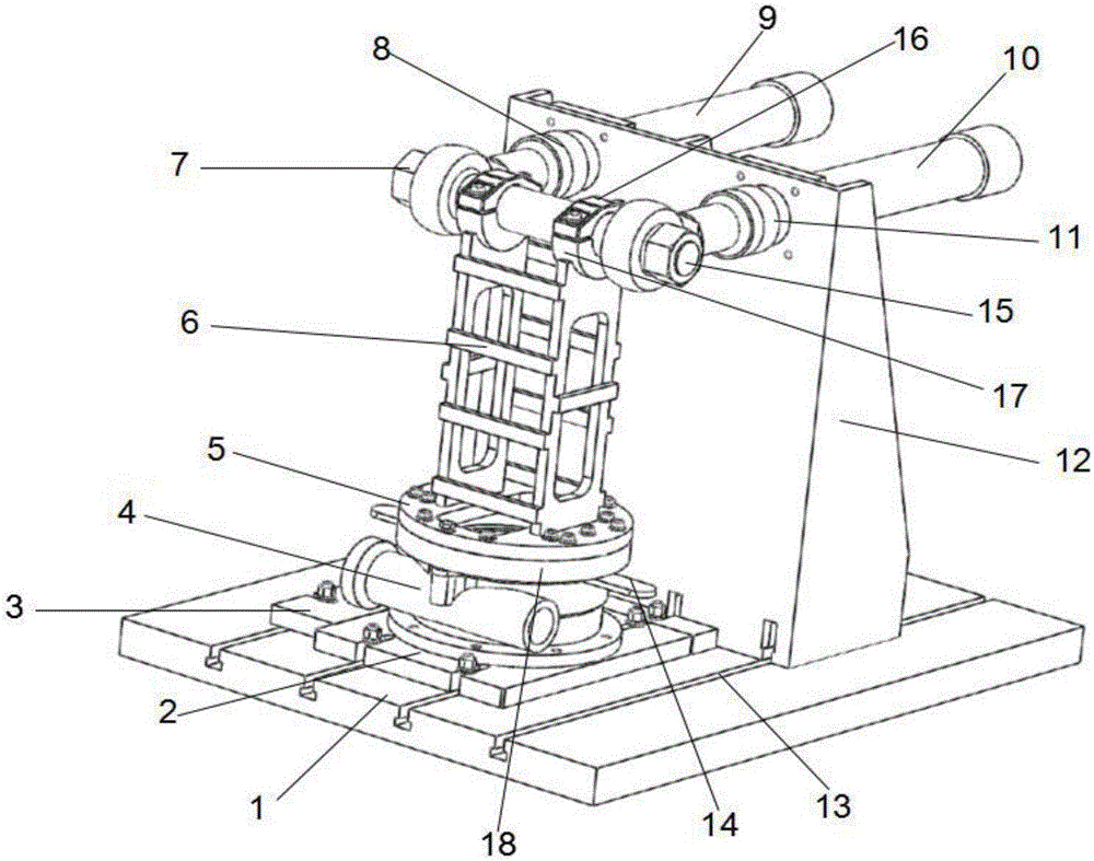
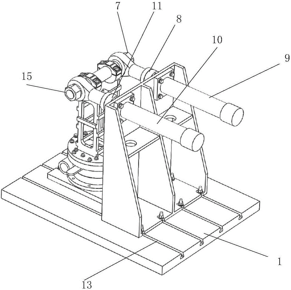
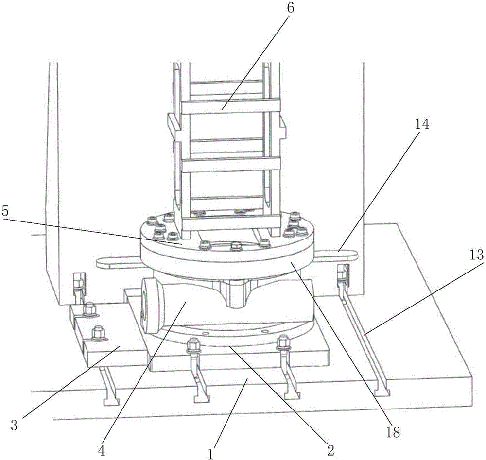
[0040] like Figure 4 As shown, the rotary reducer 4 includes a gear transmission structure, a rotary reducer housing 20 and a rotary reducer base 21, such as Figure 1 to Figure 4As shown, the rotary reducer rigidity detection device provided by the present invention includes: a base 1, a connecting seat, a first driving mechanism 9, a second driving mechanism 10, a displacement testing device (not shown in the figure) and a control center; ...


PUM


Abstract

The invention discloses a device for detecting rigidity of a gyration reduction gear. The device includes a foundation base, a connection base, a first driving mechanism, a second driving mechanism, a displacement testing device and a control center; the connection base includes a connection-base bottom base, a connection-base support column, a first actuating arm and a second actuating arm, wherein the first actuating arm and the second actuating arm transversely stretch out from two opposite sides of the top of the connection-base support column; the first driving mechanism includes a first driving part and a first retractable part, and a first force sensor is arranged on the joint between a free end of the first retractable part and the first actuating arm; the second driving mechanism includes a second driving part and a second retractable part, and a second force sensor is arranged on the joint between a free end of the second retractable part and the second actuating arm; the displacement testing device is used for testing displacement values of the tested gyration reduction gear under the effect of a testing load; the control center is in communication connection with the first driving mechanism, the second driving mechanism, the first force sensor, the second force sensor and the displacement testing device. According to the device for detecting the rigidity of the gyration reduction gear, the torsional rigidity of the gyration reduction gear and the flexible rigidity of the gyration reduction gear can be tested mechanically.

Description

technical field [0001] The invention relates to the technical field of rotary reducers, in particular to a rigidity detection device for rotary reducers. Background technique [0002] As a commonly used transmission component, the rotary reducer is widely used in many technical fields, but before applying the reducer, it is necessary to check whether the performance of the reducer meets the requirements in all aspects. Among them, during the application process of the rotary reducer, its There will be a load on it, and the rotary reducer drives the load to rotate. In order for the rotary reducer to drive the load to run smoothly, the reducer is required to have high torsional rigidity. At the same time, the load on the reducer may exert a certain amount of overturning on the reducer. In this respect, the reducer is required to have high bending rigidity. In view of the above problems, after the reducer is produced, it is necessary to test whether its torsional rigidity and b...

Claims


Application Information

Patent Timeline
Patent Type & Authority Applications(China)
IPC IPC(8): G01M13/02
CPCG01M13/025
Inventor 徐能张旭中朱正平江远财
Owner ZHEJIANG SUPCON SOLAR TECHNOLOGY CO LTD
Why Eureka
Try Eureka