
Display panel and a display device

A display panel and substrate technology, applied in the field of microelectronics, can solve the problem of performance degradation of the display panel and achieve the effect of reducing the impact

Active Publication Date: 2017-06-13
SHANGHAI TIANMA MICRO ELECTRONICS CO LTD
View PDF3 Cites 12 Cited by
  • Summary
  • Abstract
  • Description
  • Claims
  • Application Information

AI Technical Summary

Problems solved by technology

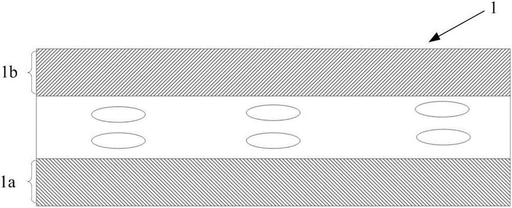
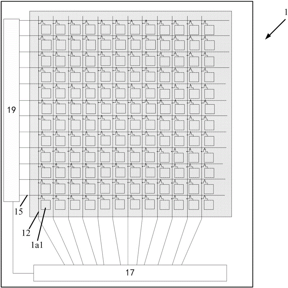
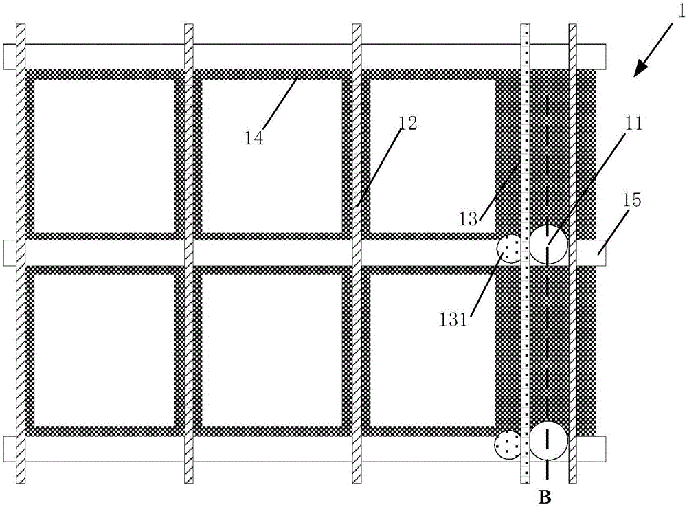
[0009] Embodiments of the present invention provide a display panel and a display device, aiming to solve the technical problem in the related art that the performance of the display panel is degraded due to the inappropriate position of the support columns, and can provide a display with a new support column structure. The panel, while avoiding the position of the support column from the touch electrode via hole, reduces the impact on the display effect of the display panel

Method used


Image

  • Display panel and a display device
  • Display panel and a display device
  • Display panel and a display device

Examples


Embodiment Construction

[0029] In order to better understand the technical solutions of the present invention, the embodiments of the present invention will be described in detail below in conjunction with the accompanying drawings.

[0030] It should be clear that the described embodiments are only some of the embodiments of the present invention, not all of them. Based on the embodiments of the present invention, all other embodiments obtained by persons of ordinary skill in the art without creative efforts fall within the protection scope of the present invention.

[0031] Terms used in the embodiments of the present invention are only for the purpose of describing specific embodiments, and are not intended to limit the present invention. As used in the embodiments of the present invention and the appended claims, the singular forms "a", "said" and "the" are also intended to include the plural forms unless the context clearly indicates otherwise.

[0032] Figure 1A A schematic diagram of the ove...


PUM


Abstract

The invention provides a display panel and a display device. The display panel comprises that at least one first prop; a first base plate is supported by a first end of the first prop; a second base plate is supported by a second end; the first prop is arranged between a data line and a touch line parallel in two adjacent sub-pixel units; the touch line comprises a strip extension part and a lateral convex part located on the strip extension part; the lateral convex part is arranged on one side of the touch line and the first prop is arranged on the other side of the touch line. The possibility of light loss in the position of the prop is reduced and the display effect of the display panel is improved.

Description

[0001] 【Technical field】 [0002] The present invention relates to the technical field of microelectronics, in particular to a display panel and a display device. [0003] 【Background technique】 [0004] Generally, a display panel includes a first substrate and a second substrate. The first substrate is arranged opposite to the second substrate. On the first substrate, a plurality of gate lines and a plurality of data lines are arranged on the side of the first substrate close to the second substrate. A line and a plurality of touch lines, wherein, a plurality of data lines and a plurality of gate lines intersect to define a plurality of sub-pixel units, and the extension directions of the plurality of data lines and the plurality of touch lines are the same. [0005] In the existing display panel, if the support column is set at the position of the touch electrode via hole, it will affect the connection performance between the touch line and the touch electrode via hole, so it...

Claims


Application Information

Patent Timeline
Patent Type & Authority Applications(China)
IPC IPC(8): G02F1/1345G02F1/1333G02F1/1339
CPCG02F1/13338G02F1/13394G02F1/13452G02F1/13396
Inventor 张敏
Owner SHANGHAI TIANMA MICRO ELECTRONICS CO LTD
Learn More