Self-locking type fastening wire clamp

A fastening and wire clip technology, applied in the direction of clamping/spring connection, electrical components, coupling devices, etc., can solve the problems of difficulty in ensuring the firmness of cable ends, time-consuming and laborious, and randomness.

Pending Publication Date: 2017-06-13
GUANGZHOU PANYU CABLE WORKS
View PDF8 Cites 6 Cited by
  • Summary
  • Abstract
  • Description
  • Claims
  • Application Information

AI Technical Summary

Problems solved by technology

[0002] It is very important to ensure the safe and stable operation of the power grid in today's society. The cable is erected on the pole or building through the street yard. The fixing of the cable end is generally to bend the cable end around the street yard and bend it in Under tension, bind or fix the bent cable ends; at present, construction workers usually use traditional methods such as manpower or simple tools to bend the cable ends and use binding wires to bind and fix the bent cable ends. Because the diameter of the cable is relatively thick, it is difficult for workers working at heights to bend and tighten the cable only by manpower or simple tools. The binding wire is generally a thin aluminum metal wire. Tightening the cable will reduce the insulation of the cable and easily The insulation outer layer causes damage, and there is no uniform standard for the binding method, which is very random, which makes it difficult to ensure the firmness of the cable end binding, and the cable end is easy to loosen and fall off from the street yard, which brings potential safety hazards
[0003] The existing technology has improved the traditional method of fixing cable ends, using clamps to fix the cable ends, but these clamps are generally connected by bolts and nuts. When working at heights, it is time-consuming and laborious for a single person to operate

Method used


Image

  • Self-locking type fastening wire clamp
  • Self-locking type fastening wire clamp
  • Self-locking type fastening wire clamp

Examples


Embodiment Construction

[0022] A self-locking fastening clamp of the present invention will be further described below in conjunction with the accompanying drawings:

[0023] It should be noted that the terms "upper", "lower", "front", "rear" and similar expressions used in this specification are only for the purpose of illustration, and are determined according to the actual situation in the embodiment.

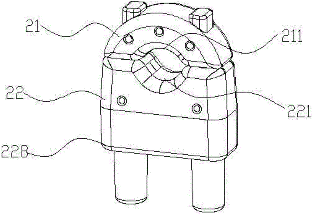
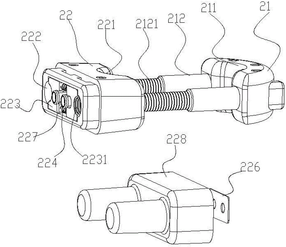
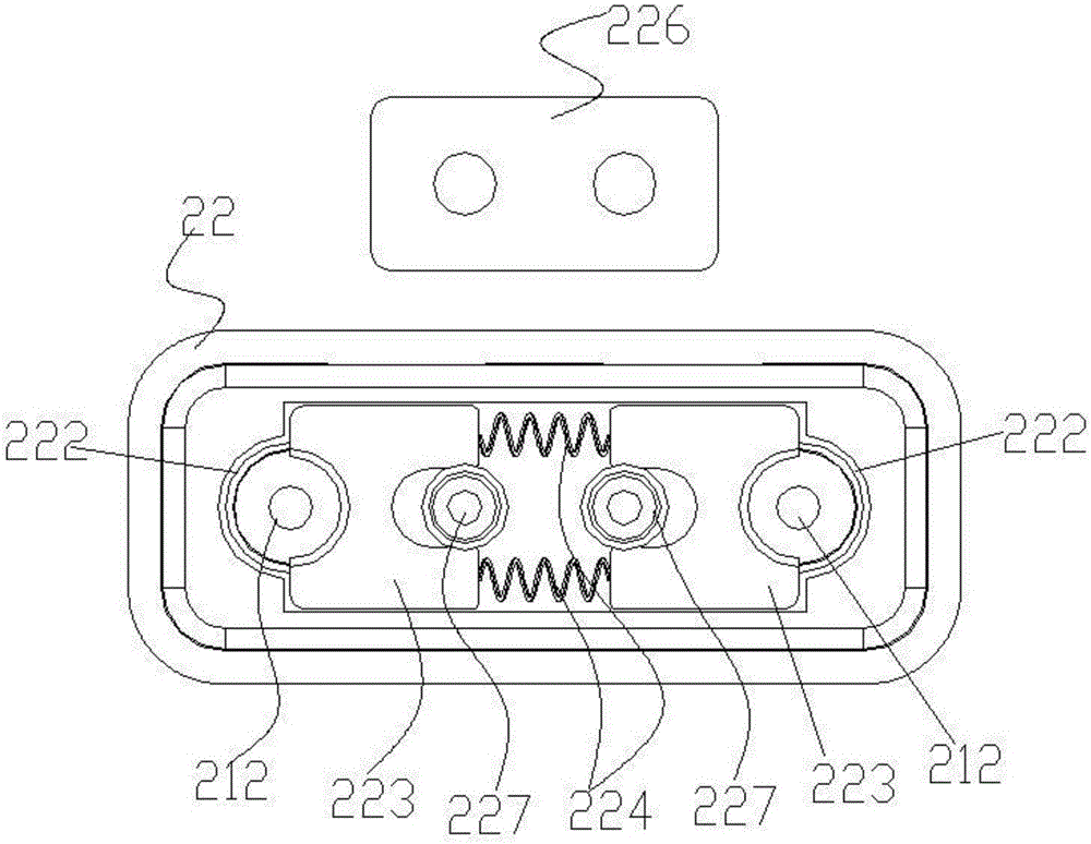
[0024] Such as Figure 1-3 As shown, a self-locking fastening clip includes a U-shaped male clip 21 and a female clip 22, the U-shaped male clip 21 and the female clip 22 are independent of each other, and the bend of the U-shaped male clip 21 is the first The clamping part 211, the front of the female clamp 22 is provided with a corresponding second clamping part 221, the first clamping part 211 and the second clamping part 221 can cooperate to clamp the cable, the two sides of the U-shaped male clamp 21 are The locking rod 212, the two sides of the second clamping part 221 on the female clip 22 ...


PUM


Abstract

A self-locking type fastening wire clamp comprises a U-shaped male clamp and a female clamp. The bent position of the U-shaped male clamp is provided with a first wire clamping portion, and the female clamp is provided with a second wire clamping portion. The first wire clamping portion and the second wire clamping portion can be matched to clamp a cable. Two side rods of the U-shaped male clamp are locking rods. Corresponding through lock holes are formed in the female clamp. Non-return ring teeth are arranged on the locking rods. Movable locking blocks are arranged on the side edges of the locking holes. The locking blocks are provided with corresponding locking teeth. The locking blocks abut against locking springs. The locking springs push the locking blocks so that the locking teeth can abut against the non-return ring teeth of the locking rods so that the locking rods can be limited to move forwards only rather than inverse motion, a non-return self-locking mechanism is formed, the U-shaped male clamp can move forwards only and cannot move backwards in the female clamp, and during operation, automatic locking can be achieved by directly inserting the U-shaped male clamp into the female clamp, loosening is easy; when the clamp is opened, the locking blocks are taken back just by pressing back the locking springs, the U-shaped male clamp can be taken out freely from the female clamp, operation is quite convenient and rapid, use is convenient, and the wire clamp is particularly suitable for high-altitude overhead transmission line construction.

Description

technical field [0001] The invention relates to the field of cable installation, in particular to a self-locking fastening clamp. Background technique [0002] It is very important to ensure the safe and stable operation of the power grid in today's society. The cable is erected on the pole or building through the street yard. The fixing of the cable end is generally to bend the cable end around the street yard and then bend it Under tension, bind or fix the bent cable ends; at present, construction workers usually use traditional methods such as manpower or simple tools to bend the cable ends and use binding wires to bind and fix the bent cable ends. Because the diameter of the cable is relatively thick, it is difficult for workers working at heights to bend and tighten the cable only by manpower or simple tools. The binding wire is generally a thin aluminum metal wire. Tightening the cable will reduce the insulation of the cable and easily damage the cable. The insu...

Claims


Application Information

Patent Timeline
Patent Type & Authority Applications(China)
IPC IPC(8): H01R4/48H01R13/639H01R13/629
CPCH01R4/48H01R13/629H01R13/639H02G3/32
Inventor 胡超强尤占山孙建吉覃丹陈雪儿卢广业张开拓王延发张仕欢郝燕邵源鹏程雪丽
Owner GUANGZHOU PANYU CABLE WORKS
Why Eureka
Try Eureka