Manufacturing method of a screw motor rotor structure

A technology of rotor structure and manufacturing method, which is applied in the manufacture of motor generators, stator/rotor bodies, electromechanical devices, etc., can solve the problems of poor dynamic response performance and large inertia, achieve good dynamic performance, weaken harmonic content, The effect of improving dynamic response performance

Active Publication Date: 2018-12-21
BEIJING RES INST OF PRECISE MECHATRONICS CONTROLS
View PDF4 Cites 0 Cited by
  • Summary
  • Abstract
  • Description
  • Claims
  • Application Information

AI Technical Summary

Problems solved by technology

In this invention, the rotor of the motor is a common structure, the inertia is relatively large, and the dynamic response performance is poor

Method used


Image

  • Manufacturing method of a screw motor rotor structure
  • Manufacturing method of a screw motor rotor structure
  • Manufacturing method of a screw motor rotor structure

Examples


Embodiment Construction

[0033] Below in conjunction with accompanying drawing and specific embodiment the present invention is described in further detail:

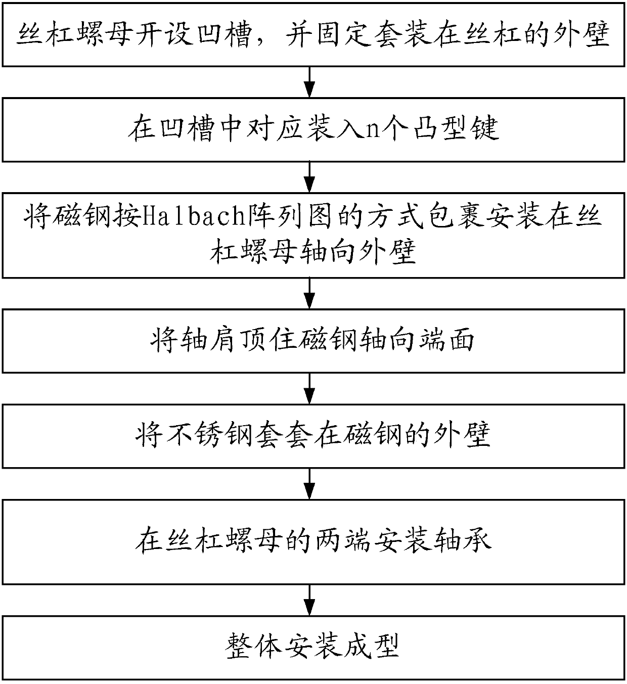
[0034] Such as figure 1 Shown is the flow chart of making the structure of the screw motor. It can be seen from the figure that a method for making the rotor structure of the screw motor includes the following steps:

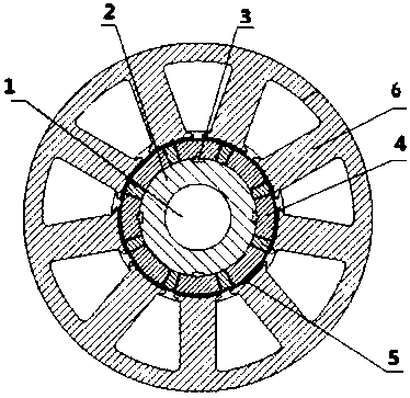
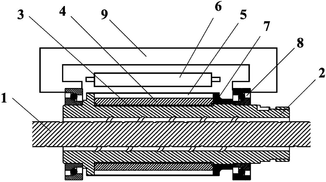
[0035] Step (1), on the axial outer wall of the lead screw nut 2, evenly open n grooves along the circumferential direction, n is a positive integer, and n is greater than or equal to 4; then the lead screw nut 2 is fixed and fitted on the lead screw 1 the outer wall;

[0036] Step (2), in step (1), put n convex keys 3 into the n grooves of the screw nut 2; put the large end of the convex key 3 into the groove, and the small end protrudes from the groove , and after the convex key 3 is installed with the groove, keep the upper surface of the large end of the convex key 3 coincident with the outer surface of the lead screw nut 2;...


PUM


Abstract

The invention relates to a manufacturing method of a screw motor rotor structure, and relates to the field of electromechanical servo mechanisms. The manufacturing method mainly comprises the following steps of (1) forming a groove in a screw nut, and fixedly sleeving on the outer wall of a screw; (2) correspondingly arranging n convex keys into the groove; (3) coating magnetic steel to the axial outer wall of the screw nut in an Halbach array graph way; (4) enabling a shaft shoulder to jack the axial end surface of the magnetic steel; (5) sleeving stainless steel onto the outer wall of the magnetic steel; (6) arranging bearings at both ends of the screw nut; (7) integrally installing and forming. The manufacturing method has the advantages that the integration design of the motor rotor and the screw is realized, and the rotation movement of the motor is converted into the linear movement of the screw; the magnetic yoke of the rotor is not needed, so that the motor has lower inertia, and good dynamic response ability.

Description

technical field [0001] The invention relates to the field of electromechanical servo mechanisms, in particular to a method for manufacturing a screw motor rotor structure. Background technique [0002] The motor is often combined with the control driver and the reducer to form an electromechanical actuator, which is used in the power output execution system of the electromechanical servo mechanism. It has the characteristics of large load and high dynamic characteristics. Especially in recent years, the power level of electromechanical actuators has become higher and higher, the zero installation size has become more and more stringent, the positive and negative strokes have become longer and longer, and the load moment has become larger and larger. Traditional electromechanical actuators have been unable to meet large loads. At the same time, the demand for its overall structural strength has also been greatly increased, so a new type of structure is urgently needed to meet...

Claims


Application Information

Patent Timeline
Patent Type & Authority Patents(China)
IPC IPC(8): H02K15/00H02K15/03
CPCH02K15/00H02K15/03
Inventor 郭喜彬魏娟赵国平郑继贵皮利萍
Owner BEIJING RES INST OF PRECISE MECHATRONICS CONTROLS
Why Eureka
Try Eureka