

Controllable rotary feed system and control method
A technology of feeding system and control method, applied in the direction of manufacturing tools, electrical components, grinding drive devices, etc., can solve problems such as no data collected, no explanation or report found, etc.
- Summary
- Abstract
- Description
- Claims
- Application Information
AI Technical Summary
Problems solved by technology
Method used
Image

Examples
Embodiment 1
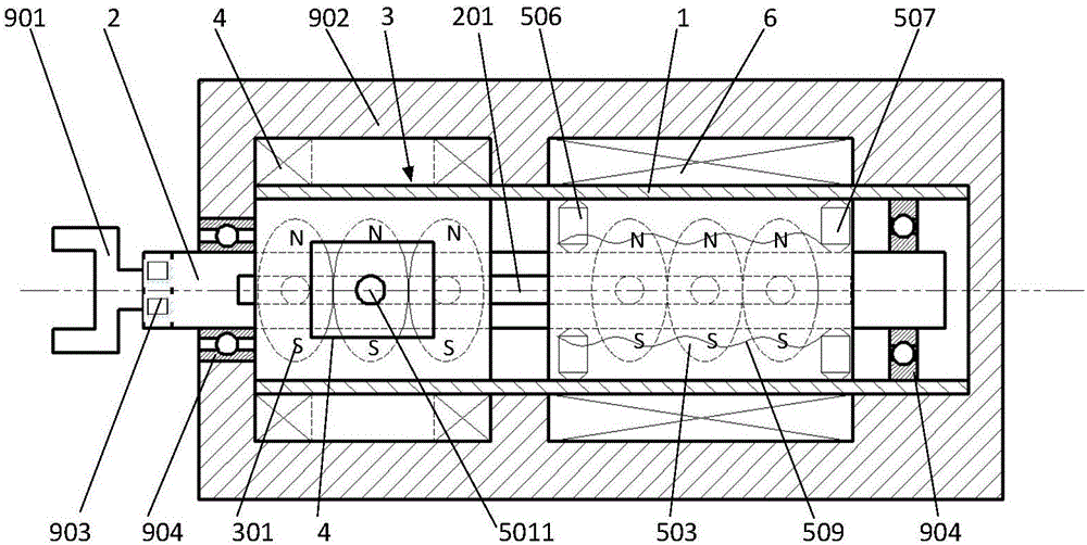
[0047] Such as figure 1 , figure 2 , Figure 4 , Figure 5 As shown, the main shaft 2 is provided with a slideway 201 extending in the axial direction; the rotating shaft of the rotating drive rotor 301 can move in translation along the slideway 201; the rotating drive coil 4 drives the rotating drive rotor 301 to rotate by means of electromagnetic excitation, and then rotates and drives the rotor The rotating shaft 301 exerts force on the slideway 201 to drive the main shaft 2 to rotate.
[0048] Neither the first positioning mechanism nor the second positioning mechanism in the second chamber tensions the sleeve and the main shaft at the same time. The magnetic pole directions of the permanent magnets in the first chamber as the rotating and driving rotors are the same, and the permanent magnets are installed on both sides of the main shaft through the rotor shaft; the rotating driving mechanism as the driving body includes four electromagnetic coils, which are divided i...
Embodiment 2
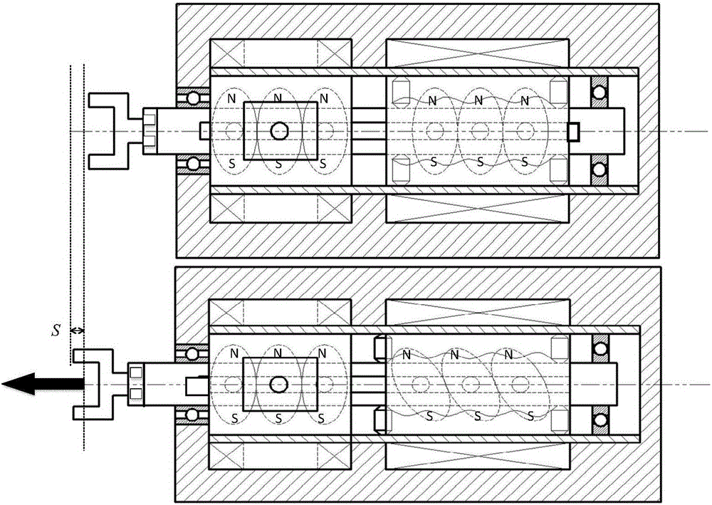
[0052] Such as image 3 As shown, the main shaft 2 is provided with a slideway 201 extending in the axial direction; the rotating shaft of the rotating drive rotor 301 can move in translation along the slideway 201; the rotating drive coil 4 drives the rotating drive rotor 301 to rotate by means of electromagnetic excitation, and then rotates and drives the rotor The rotating shaft 301 exerts force on the slideway 201 to drive the main shaft 2 to rotate.
[0053]Neither the first positioning mechanism nor the second positioning mechanism in the second chamber tensions the sleeve and the main shaft at the same time. The magnetic pole directions of the permanent magnets in the first chamber as the rotating drive rotor are the same, and the permanent magnets are sheathed on the main shaft; the rotating drive coil as the driving body includes four electromagnetic coils, which are divided into left and right, upper and lower groups from the axial view. When the left and right grou...
Embodiment 3
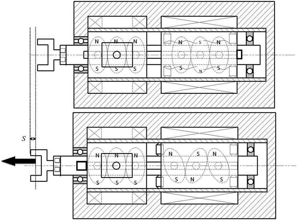
[0057] As shown in FIG. 6 and FIG. 7 , the rotary drive rotor 301 is tightly sleeved on the main shaft 2 ; the rotary drive coil 4 drives the rotary drive rotor 301 to rotate by means of electromagnetic excitation, and then the rotary drive rotor 301 drives the main shaft 2 to rotate.
[0058] Neither the first positioning mechanism nor the second positioning mechanism in the second chamber tensions the sleeve and the main shaft at the same time. The permanent magnets in the first chamber are fan-shaped permanent magnets as fan-shaped magnets, and the magnetic poles of adjacent permanent magnets are in opposite directions, and all the permanent magnets form a magnetic turntable and are installed on the main shaft. The driving body includes 6 electromagnetic coils, but is not limited to this number. The 6 electromagnetic coils are divided into three groups and arranged in the middle of the front and rear magnetic turntables. When the three groups of electromagnetic coils are su...
PUM
 Abstract
Description
Claims
Application Information