Motor driving circuit, motor driving method and electronic equipment

A motor drive and circuit technology, applied in the direction of excitation or armature current control, which can solve the problems of inability to exert the transient performance of the motor and small driving voltage.

Inactive Publication Date: 2017-06-13
MEIZU TECH CO LTD
View PDF9 Cites 9 Cited by
  • Summary
  • Abstract
  • Description
  • Claims
  • Application Information

AI Technical Summary

Problems solved by technology

[0004] Embodiments of the present invention provide a motor drive circuit, method and electronic equipment, which are used to solve the problems of the existing motor drive circuit that the drive voltage provided is small and the transient performance of the motor cannot be exerted

Method used


Image

  • Motor driving circuit, motor driving method and electronic equipment
  • Motor driving circuit, motor driving method and electronic equipment
  • Motor driving circuit, motor driving method and electronic equipment

Examples


Embodiment 1

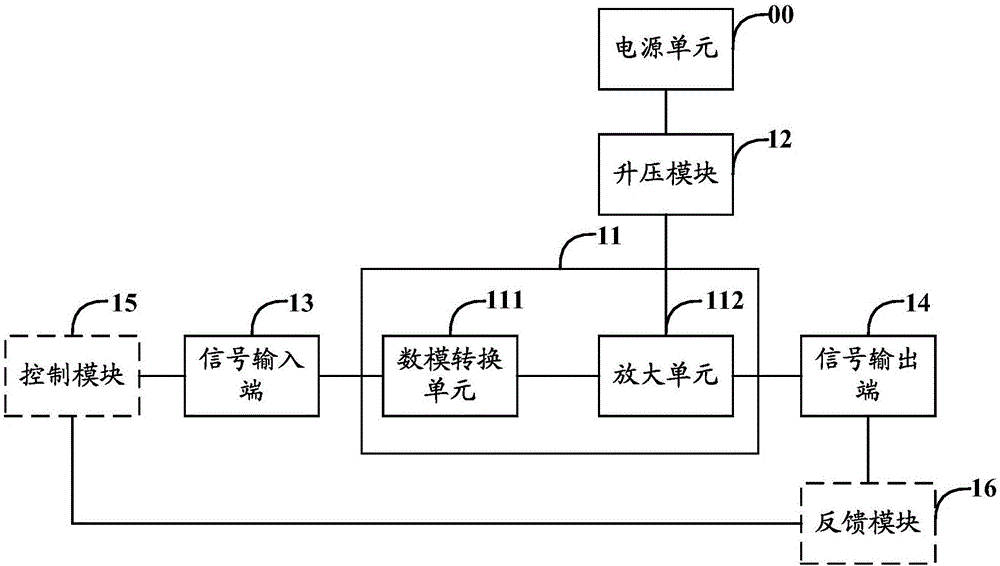
[0025] In order to solve the problems existing in the existing motor driving circuit that the provided driving voltage is small and the transient performance of the motor cannot be utilized, an embodiment of the present invention provides a motor driving circuit, which can be set in a corresponding Electronic devices, such as mobile phones, tablet computers, smart watches and other electronic devices, such as figure 1 As shown, it is a schematic structural diagram of the motor drive circuit described in Embodiment 1 of the present invention. Specifically, by figure 1 It can be seen that the motor drive circuit may include a drive module 11, a boost module 12, and a signal input terminal 13 and a signal output terminal 14 connected to the drive module 11, wherein the drive module 11 is electrically connected to the power supply unit 00, The drive module 11 may include a digital-to-analog conversion unit 111 and an amplification unit 112;

[0026] The digital-to-analog convers...

Embodiment 2

[0059] Based on the same inventive concept as that of Embodiment 1 of the present invention, Embodiment 2 of the present invention provides a motor driving method, such as Image 6 As shown, it is a schematic flowchart of the motor driving method described in the embodiment of the present invention. Specifically, by Image 6 It can be seen that the motor driving method described in the embodiment of the present invention may include:

[0060] Step 601: Receive a digital audio signal for driving the motor, and convert the digital audio signal into an analog signal;

[0061] Step 602: Raise the input voltage provided by the power supply, and amplify the analog signal based on the raised input voltage;

[0062] Step 603: Send the amplified analog signal to the motor.

[0063] That is to say, in the embodiment of the present invention, the digital audio signal for driving the motor can be received, and the digital audio signal can be converted into an analog signal; the input v...


PUM


Abstract

The invention discloses a motor driving circuit, a motor driving method and electronic equipment. The motor driving circuit comprises a drive module, a booster module, a signal input end and a signal output end, wherein the signal input end and the signal output end are connected with the drive module; the booster module is electrically connected with a power supply unit; the drive module comprises a digital-to-analogue conversion unit and an amplifying unit; the digital-to-analogue conversion unit is used for receiving a digital audio signal through the signal input end and converting the digital audio signal into an analogue signal; the amplifying unit is used for amplifying the analogue signal and transmitting the amplified analogue signal to a motor through the signal output end; the booster module is used for boosting input voltage provided by the power supply unit and outputting the boosted input voltage to the amplifying unit. Therefore, driving voltage output by the motor driving circuit can be increased, the start and stop time of the corresponding motor is shortened and the transient performance of the motor can be developed.

Description

technical field [0001] The invention relates to the technical field of motor driving, in particular to a motor driving circuit, method and electronic equipment. Background technique [0002] At present, the industry often uses a drive motor drive circuit based on a push-pull circuit to drive the motors in various electronic devices. The drive voltage output by the motor drive circuit in this way is small, which may lead to a small vibration of the corresponding motor. The problem of weak vibration feeling and long start and stop time also makes it difficult to achieve diverse vibration effects. [0003] That is to say, the existing motor driving circuit has the problems of providing a relatively small driving voltage and failing to exert the transient performance of the motor. Contents of the invention [0004] Embodiments of the present invention provide a motor driving circuit, method and electronic equipment, which are used to solve the problems of the existing motor d...

Claims


Application Information

Patent Timeline
Patent Type & Authority Applications(China)
IPC IPC(8): H02P7/06
CPCH02P7/06
Inventor 杨俊王韡
Owner MEIZU TECH CO LTD
Why Eureka
Try Eureka