
A two-stage continuously adjustable concentrating photothermal device

A two-stage, photothermal technology, applied in the direction of electric heating devices, lighting devices, components of lighting devices, etc., can solve the problem of reducing the service life of the light source and device stability, affecting the service life of the light source and optical performance, increasing the light source and system Manufacturing costs and other issues to achieve the effect of improving energy utilization, better protecting the light source, and prolonging the life

Active Publication Date: 2019-08-23
HUAZHONG UNIV OF SCI & TECH
View PDF6 Cites 0 Cited by
  • Summary
  • Abstract
  • Description
  • Claims
  • Application Information

AI Technical Summary

Problems solved by technology

Although it meets the requirements of some production research to a certain extent, there are still some deficiencies: First, the limit temperature is limited by the heat transfer mode of the first-level direct light source, which is lower than the temperature limit of many traditional resistance furnaces, and still cannot Meet the needs of many practical applications; second, the light source and heat source are in the furnace body, which affects the service life and optical performance of the light source on the one hand, and increases the manufacturing cost of the light source and system on the other hand, making the equipment counterfeit expensive; The temperature adjustment and the control of the heating rate all depend on the adjustment of the input power of the light source, which greatly reduces the service life of the equipment; the fourth is that the optical adjustment mainly depends on the potentiometer to adjust the input power, so that the optical device cannot work at the rated power , which also reduces the service life of the light source and the stability of the device to a certain extent

Method used


Image

  • A two-stage continuously adjustable concentrating photothermal device
  • A two-stage continuously adjustable concentrating photothermal device

Examples


Embodiment Construction

[0034] The principles and features of the present invention are described below in conjunction with the accompanying drawings, and the examples given are only used to explain the present invention, and are not intended to limit the scope of the present invention.

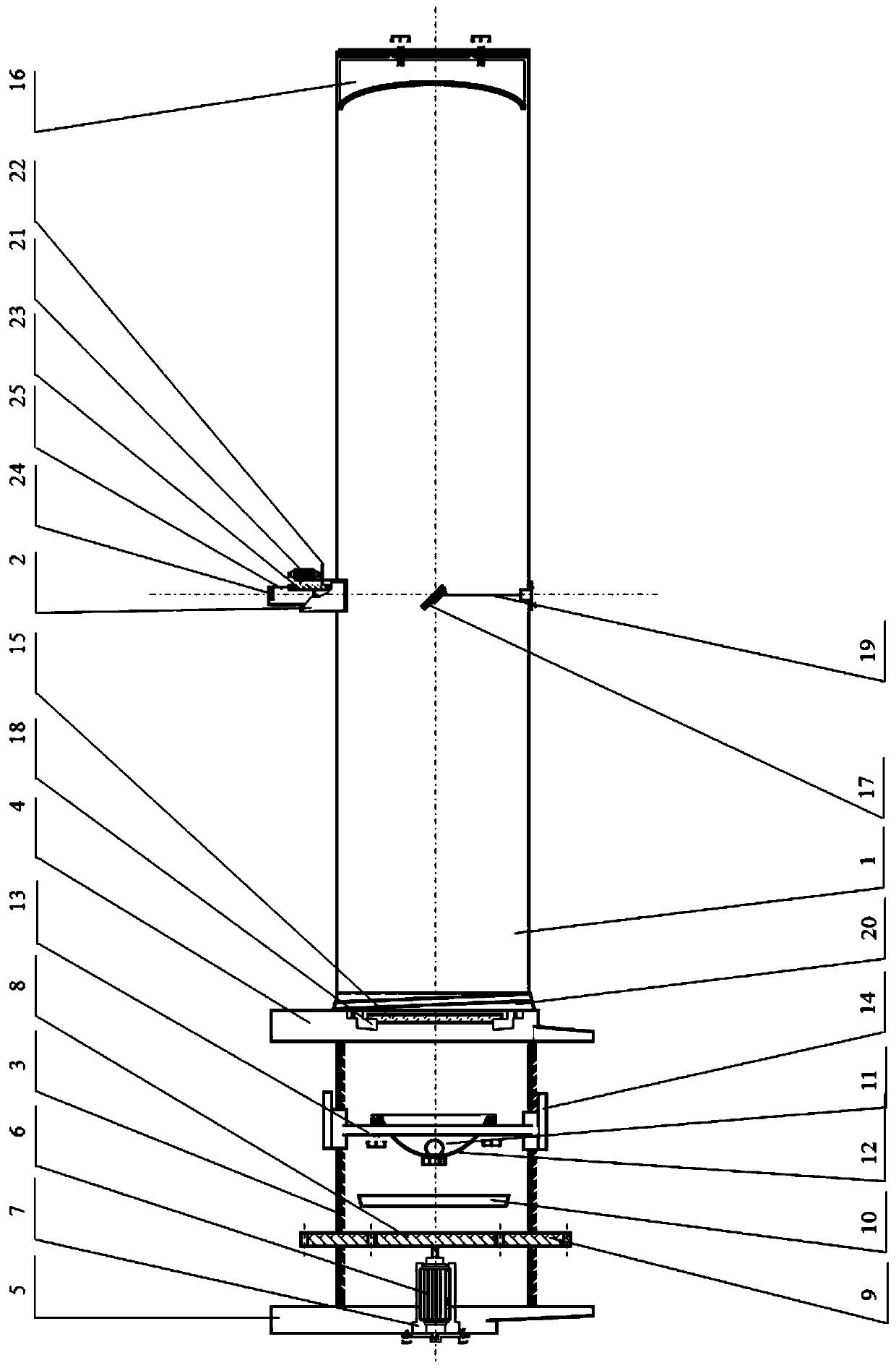
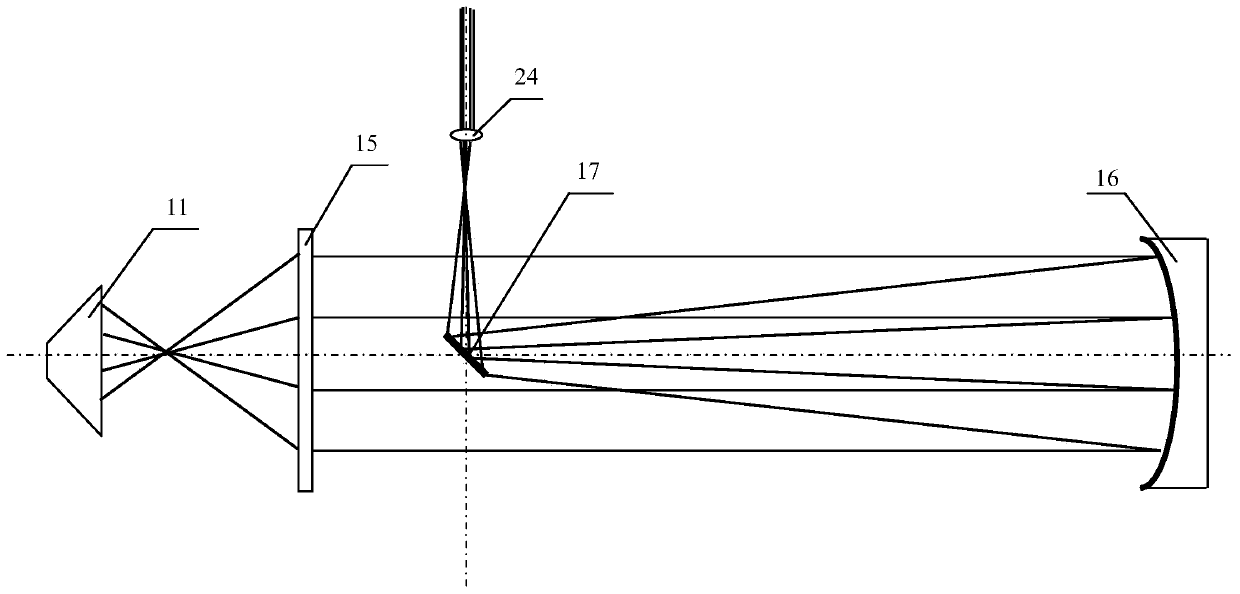
[0035] Such as figure 1 As shown, a two-stage continuously adjustable concentrating photothermal device includes an initial stage adjustment assembly, a light source assembly, a light collection assembly, a primary lens barrel 1, a secondary stage adjustment assembly, a secondary lens barrel 2 and a light output assembly.

[0036] One end of the primary adjustment assembly is connected to one end of the primary lens barrel 1, the light source assembly is arranged in the initial adjustment assembly, and the initial adjustment assembly can drive the light source assembly in the initial adjustment assembly axial movement.

[0037] The condensing assembly is arranged in the primary lens barrel 1, the secondary lens bar...


PUM


Abstract

The present invention relates to a two-stage continuously adjustable concentrating photo-thermal device. The device comprises a first-stage regulation module, a light source module, a concentrating module, a first-class lens barrel, a second-stage regulation module, a second-class lens barrel and a light exit module. One end of the first-stage regulation module is connected with one end of the first-class lens barrel, and the light source module is arranged in the first-stage regulation module and drives the light source module to perform axial motion in the first-stage regulation module. The concentrating module is arranged in the first-class lens barrel, the second-class lens barrel is arranged at the side wall of the first-class lens barrel, the light exit module is arranged in the second-class lens barrel, light ray reflected by the concentrating module enters the second-class lens barrel and exits from the light exit module, and the second-stage regulation module is arranged at the side wall of the second-class lens barrel and drives the light exit module to lift the motion. The two-stage continuously adjustable concentrating photo-thermal device separates the light source module from a heated object to protect the light source well and prolong the life of the light source, the first-stage regulation module and the second-stage regulation module are coordinated with each other to realize continuous regulation, and the light source energy is focused through the concentrating module to improve the light source utilization rate.

Description

technical field [0001] The invention relates to the field of concentrating light and heat, in particular to a two-stage continuously adjustable concentrating light and heat device. Background technique [0002] With the development of science and technology and the progress of modern material preparation technology, the requirements for heating temperature and heating rate are getting higher and higher. It is difficult for the traditional resistance heating furnace to meet the requirements of actual scientific research and manufacturing. [0003] In the fields of fuel combustion, gasification, pyrolysis, etc., in order to establish accurate prediction models, it is necessary to obtain particle heating rates as high as 10 during the heating process. 2 ~10 5 ℃ / s, while the temperature rise rate of traditional resistance heating devices generally does not exceed 50°C / s, which is difficult to meet the temperature rise requirements and is extremely time-consuming and energy-cons...

Claims


Application Information

Patent Timeline
Patent Type & Authority Patents(China)
IPC IPC(8): F21V14/02H05B3/00
Inventor 胡松李寒剑池寰瀛向军苏胜汪一江龙徐凯
Owner HUAZHONG UNIV OF SCI & TECH
Learn More