


Quick Research
Generate reliable direction feasibility study reports for your R&D in just a few steps.

Technical Q&A
Discover and master advanced knowledge NOW. Basics, ideas, possibilities, all at once.

Find Solutions
As an expert in R&D theories, this can generate solutions to your technical problems instantly.

Evaluate Feasibility
Analyze your overall solution with one click, know your potential R&D risks in advance.

Monitor Landscape
Get weekly tech updates, stay abreast of the latest tech innovations and key insights.
Calculation method and device for required output power of dual-motor system and dual-motor system
A technology of output power and demand power, applied in the field of dual motor system, to achieve the effect of taking into account both power and economy
- Summary
- Abstract
- Description
- Claims
- Application Information
AI Technical Summary
Problems solved by technology
Method used
Image

Examples
Embodiment 1
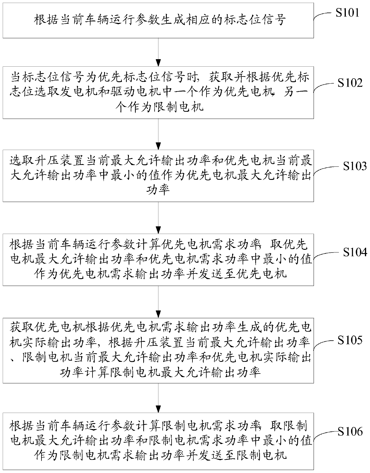
[0045] Embodiment 1 of the present invention discloses a method for calculating the required output power of a dual-motor system. The flow chart is as follows: figure 1 As shown, the calculation methods include:
[0046]S101, generating a corresponding flag signal according to the current vehicle operating parameters;
[0047] In the process of executing step S101, a corresponding flag signal is generated according to the current vehicle operating parameters, wherein the current vehicle operating parameters include the current vehicle speed, the current vehicle speed change value, the current accelerator pedal opening, the brake pedal braking force and the remaining battery power Percentage, the flag signal includes the priority flag signal and no priority flag signal, the priority flag signal also includes the priority generator flag signal and the priority drive motor flag signal.
[0048] S102, when the flag bit signal is a priority flag bit signal, acquire and select one ...
Embodiment 2
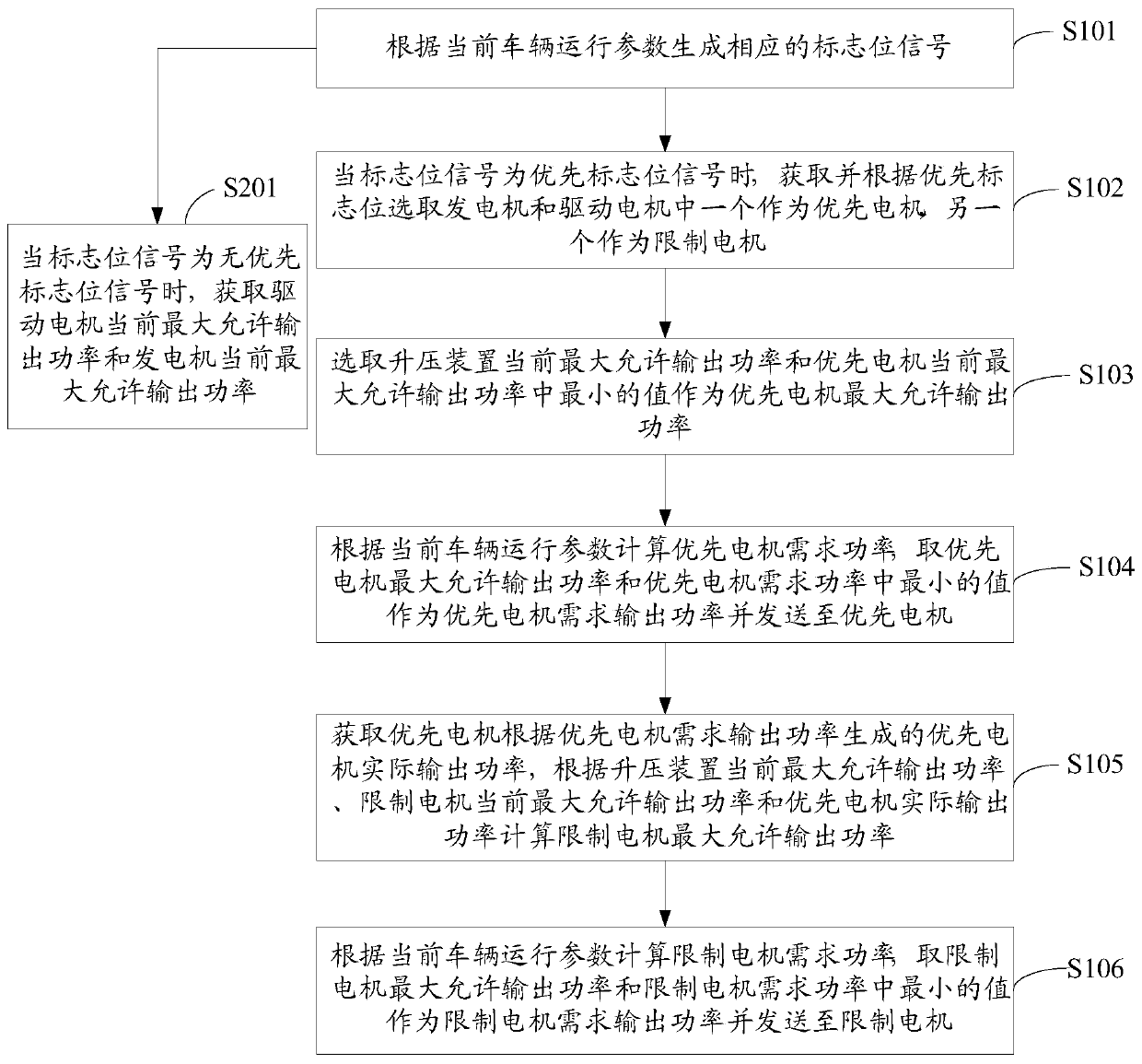
[0057] Based on the method for calculating the required output power of a dual-motor system disclosed in Embodiment 1 of the present invention, Embodiment 2 of the present invention discloses another method for calculating the required output power of a dual-motor system. The flow chart is as follows figure 2 As shown, the calculation methods include:
[0058] S101, generating a corresponding flag signal according to the current vehicle operating parameters;
[0059] S201. Obtain the current maximum allowable output power of the drive motor and the current maximum allowable output power of the generator when the flag signal is a no-priority flag signal;
[0060] In the process of executing step S201, when it is judged that the flag signal is no priority flag signal, it means that it is in the parking state, and the current maximum allowable output power of the drive motor and generator is obtained directly.
[0061] S102, when the flag bit signal is a priority flag bit signa...
Embodiment 3
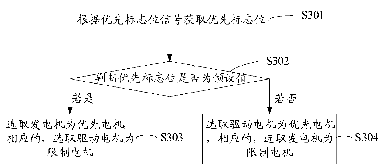
[0069] Based on the calculation method of the required output power of the dual-motor system disclosed in Embodiment 1 and Embodiment 2 of the present invention above, as figure 1 and figure 2 In the shown step S102, obtain and select one of the generator and the drive motor as the priority motor and the other as the specific execution process of the limit motor according to the priority flag bit, such as image 3 shown, including the following steps:
[0070] S301. Obtain the priority flag according to the priority flag signal;
[0071] S302, judging whether the priority flag bit is a preset value;
[0072] S303, if yes, select the generator as the priority motor, and correspondingly, select the driving motor as the restricted motor;
[0073] S304, if not, select the driving motor as the priority motor, and correspondingly, select the generator as the restricted motor.
[0074] The calculation method for the required output power of the dual-motor system disclosed in the...
PUM
 Abstract
Description
Claims
Application Information
 - R&D Engineer
- R&D Manager
- IP Professional
- Industry Leading Data Capabilities
- Powerful AI technology
- Patent DNA Extraction
Browse by: Latest US Patents, China's latest patents, Technical Efficacy Thesaurus, Application Domain, Technology Topic, Popular Technical Reports.
© 2024 PatSnap. All rights reserved.Legal|Privacy policy|Modern Slavery Act Transparency Statement|Sitemap|About US| Contact US: help@patsnap.com