Biaxial loading four-line contact pure rolling cylindrical roller fatigue life testing machine
A cylindrical roller and fatigue life technology, which is applied in the field of dual-axis loading four-wire contact pure rolling cylindrical roller fatigue life testing machine, can solve the problems of wide size range and asymmetry of the tested rollers
- Summary
- Abstract
- Description
- Claims
- Application Information
AI Technical Summary
Problems solved by technology
Method used
Image
Examples
Embodiment 1
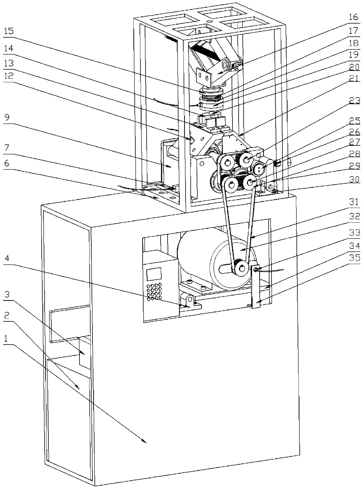
[0024] Embodiment one: see figure 1, the biaxial loading four-line contact pure rolling cylindrical roller fatigue life testing machine includes a machine base 1, an oil tank 2, an oil pump 3, a motor 32, a test core device, a loading mechanism, a transmission mechanism and a data acquisition system. An oil tank 2, an oil pump 3 and a motor 32 are arranged in the base 1, and an upper bracket 6 is installed on the base 1; In the upper bracket 6; the oil tank 2 is connected to the test core device through the oil pump 3, and oil is supplied to it for lubrication; The mechanism is connected to drive the core device of the test to realize the rolling fatigue test of cylindrical rollers.
Embodiment 2
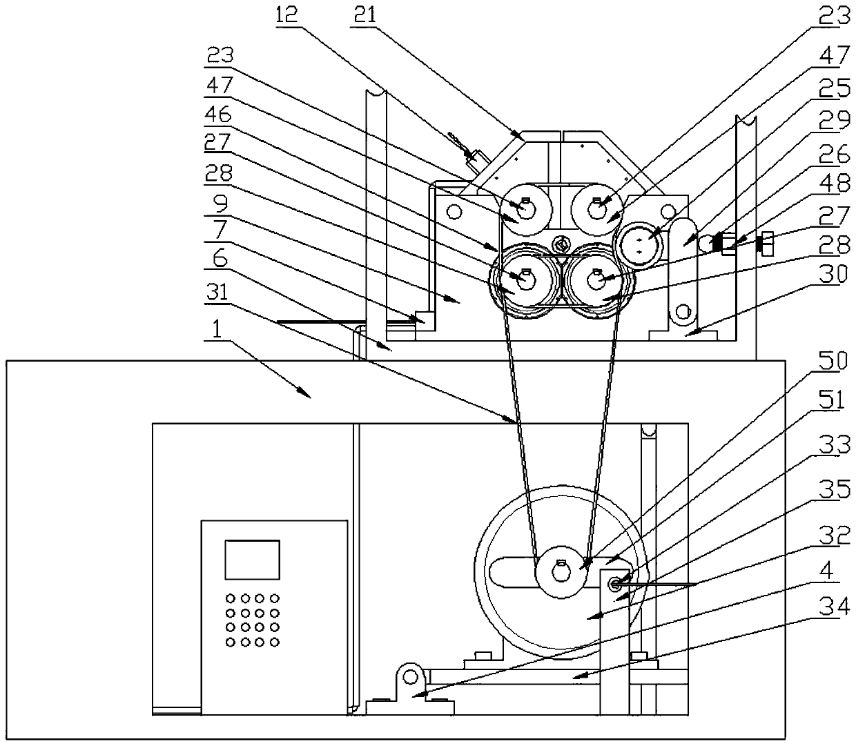
[0025] Embodiment two: see figure 2 , the transmission mechanism includes: motor base 4, motor bottom plate 34, motor 32, speed sensor bracket 35, speed sensor 33, rotating baffle 51, output shaft timing pulley 50, main timing belt 31, two supporting shafts double Timing pulley 28, two supporting shafts 27, secondary timing belt 46, two loading shafts synchronous pulley 47, two loading shafts 23, tensioning pulley 25, tensioning pulley bracket 29, tensioning pulley seat 30, ball top Bolt 26, ball head top bolt locking bolt 48; described motor seat is connected on the second floor of support 1 by thread, and described motor bottom plate 34 is installed on the motor seat 4 by hinge shaft; Described motor 32 is threaded on motor On the bottom plate 34, the up and down position of the motor 32 is adjusted by bolts; the output shaft synchronous pulley 50 is installed on the output shaft end of the motor 32 by a key connection; the two supporting shaft double synchronous pulleys 28...
Embodiment 3
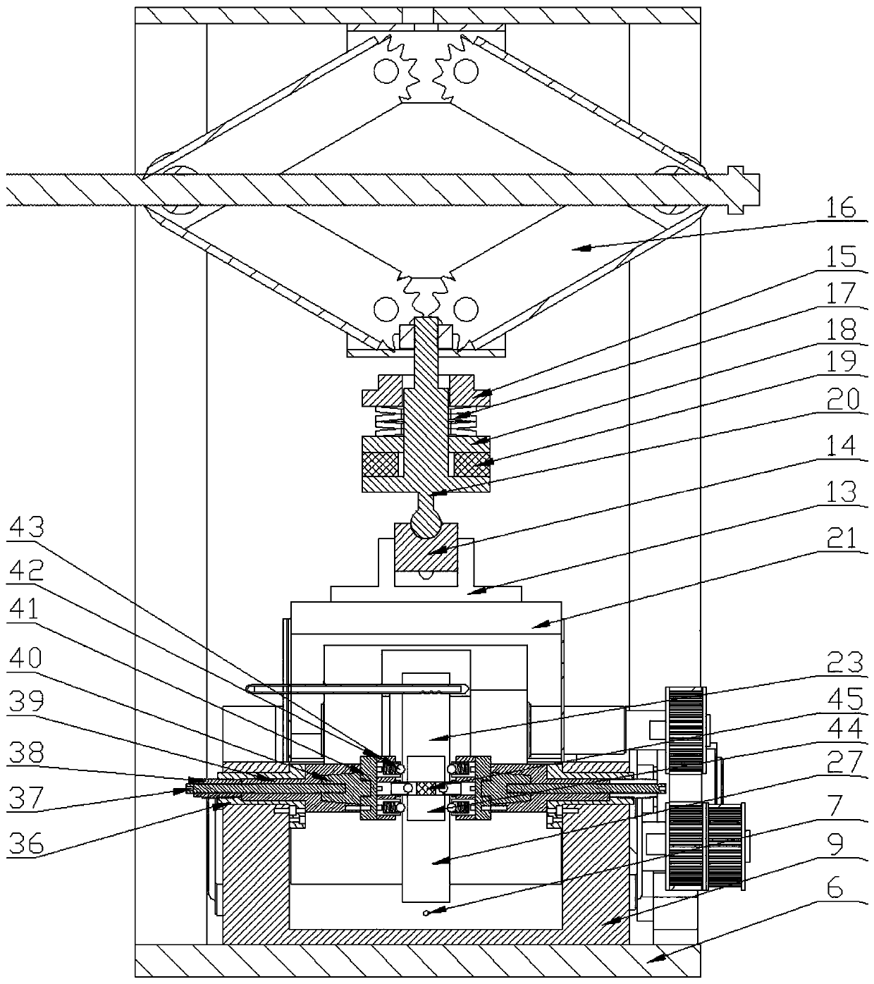
[0026] Embodiment three: see image 3 , the loading mechanism includes: scissor jack 16, spring block one 15, disc spring 17, spring block two 18, pressure sensor 19, ball head loading rod 20, pressure block 14, two pressure block guide grooves 13 ; The scissor jack 16 is threaded on the top of the upper bracket 6; the ball head loading rod 20 is installed on the bottom of the scissor jack 16 by threads; the spring block one 15, disc spring 17, spring block 218. The pressure sensor 19 is stacked on the central axis of the ball head loading rod 20; the two pressure block guide grooves 13 are respectively threaded on the two box upper covers 21, and the pressure block 14 is placed on the two In the first pressure block guide groove 13, when loading, the ball head of the ball head loading rod 20 contacts the concave spherical surface above the pressure block 14, and then the convex spherical surface below the pressure block 14 exerts pressure on the two pressure block guide groov...
PUM
 Abstract
Description
Claims
Application Information
 - R&D
- Intellectual Property
- Life Sciences
- Materials
- Tech Scout
- Unparalleled Data Quality
- Higher Quality Content
- 60% Fewer Hallucinations
Browse by: Latest US Patents, China's latest patents, Technical Efficacy Thesaurus, Application Domain, Technology Topic, Popular Technical Reports.
© 2025 PatSnap. All rights reserved.Legal|Privacy policy|Modern Slavery Act Transparency Statement|Sitemap|About US| Contact US: help@patsnap.com


