Improved clamping mechanism of fatigue testing machine for in-situ imaging of synchronous radiation light source

A fatigue testing machine and clamping mechanism technology, used in workpiece clamping devices, optical testing of flaws/defects, material analysis using radiation, etc. The sample is firm, easy to install, and the image has a high signal-to-noise ratio.

Active Publication Date: 2016-07-13
SOUTHWEST JIAOTONG UNIV
View PDF7 Cites 4 Cited by
  • Summary
  • Abstract
  • Description
  • Claims
  • Application Information

AI Technical Summary

Problems solved by technology

However, it is found that during the fatigue test of the fatigue testing machine, due to the severe vibration generated, and the clamping of the sample by the clamp during the test often causes loosening due to the severe vibration.
In addition, there is no further adjustment method after the plastic deformation of the sample, so that the test cannot go on smoothly. Based on this actual situation, it is very necessary to further improve the clamping mechanism of the fixture

Method used


Image

  • Improved clamping mechanism of fatigue testing machine for in-situ imaging of synchronous radiation light source
  • Improved clamping mechanism of fatigue testing machine for in-situ imaging of synchronous radiation light source
  • Improved clamping mechanism of fatigue testing machine for in-situ imaging of synchronous radiation light source

Examples


Embodiment

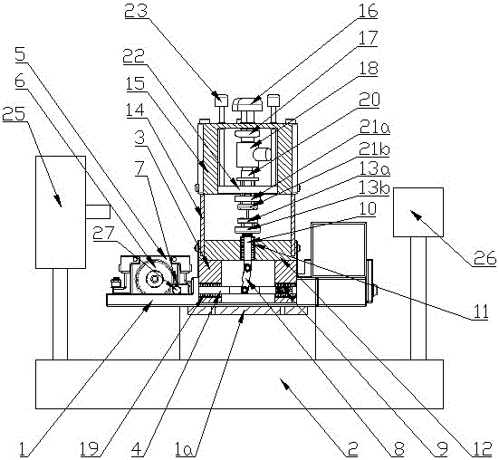
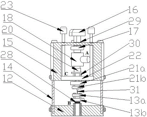
[0022] figure 1 , figure 2 Shown is a fatigue testing machine for in-situ imaging with a synchrotron radiation light source, which consists of: the cross 1a at the bottom of the bottom plate 1 is fitted on the platform 2 of the synchrotron radiation light source, and a cylindrical base 3 is fixed in the middle of the upper surface of the bottom plate 1 The push rod 4 is installed on the left wall and the right wall of the base 3 through a horizontal linear bearing-19; the left side of the base plate 1 upper surface is equipped with a servo motor 5, and the cam 6 is installed on the servo motor 5 shaft; the left end of the push rod 4 Hole is opened and rolling bearing shaft 27 is housed, and bearing shaft 27 is equipped with rolling bearing 7 and contacts with the right edge of cam 6, and the middle part of push rod 4 is hinged with the lower end of connecting rod 8, and the right end of push rod 4 is connected to the right side of base 3 by spring 9. on the wall.

[0023] T...


PUM


Abstract

The invention discloses an improved clamping mechanism of a fatigue testing machine for in-situ imaging of a synchronous radiation light source, which is arranged on a platform cylindrical base of the synchronous radiation light source. The improved clamping mechanism comprises a sample clamping unit and a plastic deformation additional adjusting unit, wherein the sample clamping unit is vertically arranged along the axle wire of the base of the fatigue testing machine and is divided into two parts of a lower clamping head section and an upper clamping head section, and the upper clamping head section is provided with the plastic deformation additional adjusting unit. Compared with a fatigue testing machine in the previous generation, the improved clamping mechanism of the fatigue testing machine for the in-situ imaging of the synchronous radiation light source, disclosed by the invention, is further improved, and the properties of buffer vibration attenuation and noise reduction of a system are increased; on the premise that load is fully enabled to be applied to a sample, the integral bearing performance of the fatigue testing machine is ensured; the plastic deformation additional adjusting unit can be used for adjusting the size of an applied force after plastic deformation of the sample happens in compaison with the fatigue testing machine in the previous generation, detailed problems in a test implementing process are more detailedly considered.

Description

technical field [0001] The invention relates to a sample clamping mechanism and installation and experiment method of a fatigue testing machine which uses a synchrotron radiation light source to perform in-situ imaging. Background technique [0002] For a long time, people have carried out a lot of research on the fatigue damage of engineering structures. It is generally believed that the fatigue life is mainly consumed in the stages of crack initiation and short crack growth. Macroscopically, the propagation behavior of short cracks changes with the increase of crack length, and microscopically, it is also affected by factors such as metal microstructure and environment, coupled with crack closure and small crack effects, etc. The problem of short crack propagation becomes very complicated. In order to better explore the relationship between the crack growth process and microstructure changes and macroscopic mechanical properties, and to provide a more reliable theoretica...

Claims


Application Information

Patent Timeline
Patent Type & Authority Applications(China)
IPC IPC(8): B25B11/00G01N21/84G01N21/88G01N23/04
CPCB25B11/00G01N21/84G01N21/88G01N23/04
Inventor 吴圣川张思齐张卫华
Owner SOUTHWEST JIAOTONG UNIV
Why Eureka
Try Eureka