Adjustable multifunctional high-speed debris flow friction test device and test method thereof

A test device and technology of debris flow, applied in the field of adjustable multifunctional high-speed debris flow friction test device, can solve the problems of inability to reveal the phenomenon of high-speed remote debris flow friction and breakage, particle collision and separation, failure to reach high-speed movement, Problems such as particle breakage changes and collision separation in debris flow cannot be observed

Inactive Publication Date: 2016-09-28
SOUTHWEST JIAOTONG UNIV
View PDF4 Cites 4 Cited by
  • Summary
  • Abstract
  • Description
  • Claims
  • Application Information

AI Technical Summary

Problems solved by technology

However, most of the existing test devices are simple and variable-angle chute, and the particulate matter can only slide down from a static state, which cannot reach the high-speed movement in the actual situation, let alone observe the fragmentation of debris flow particles caused by bottom friction during high-speed movement. Variation and Collision Separation
In short, the current test device can only reveal the relationship between the movement speed of the debris flow and the accumulation form, but it cannot reveal the frictional breakage and particle collision and separation phenomena during the movement of the high-speed remote debris flow, let alone measure the different Changes in the coefficient of dynamic friction of the sliding surface under normal pressure and different speeds; thus, it cannot provide accurate and reliable test basis for the prevention and control of debris flow disasters

Method used


Image

  • Adjustable multifunctional high-speed debris flow friction test device and test method thereof
  • Adjustable multifunctional high-speed debris flow friction test device and test method thereof

Examples


Embodiment

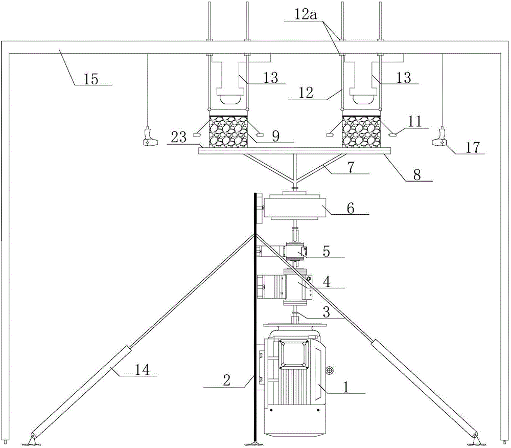
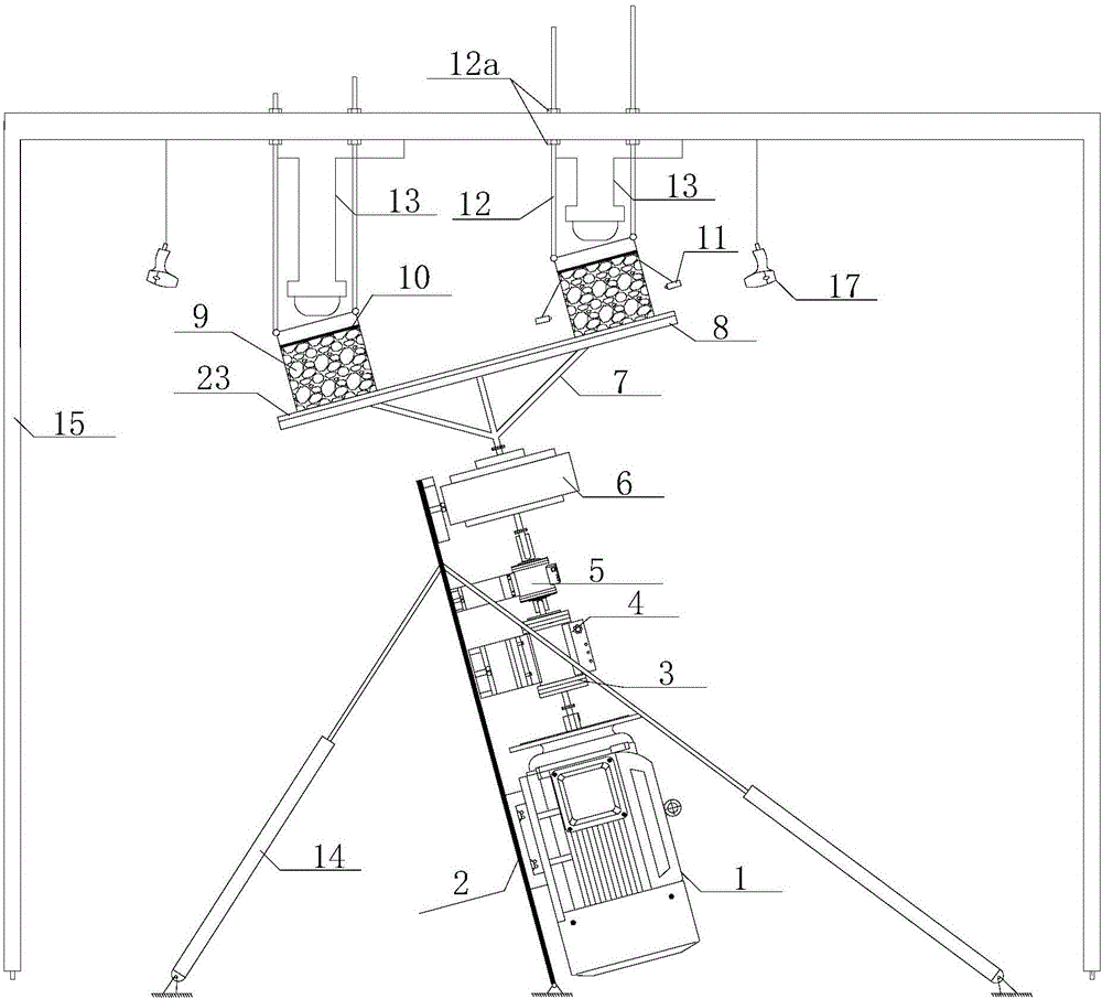
[0031] Figure 1-Figure 2 Shown, one embodiment of the present invention is: an adjustable multifunctional debris flow movement crushing test device, characterized in that:

[0032] The bottom of the vertical steel plate 2 is hinged to the ground, the upper part of the steel plate 2 is hinged to the top of the telescopic connecting rod 14, and the bottom end of the connecting rod 14 is hinged to the ground; 4, torque sensor 5 and bearing 6, the shaft of the motor 1 is connected to the lower end of the main shaft through the reducer 4 and the torque sensor 5 in sequence, the upper end of the main shaft is connected to the lower part of the bracket 7 through the bearing 6, and the upper part of the bracket 7 is fixed with a hollow circle disk 8;

[0033] Two square, bottomless, and transparent model boxes 9 are symmetrically placed on the top of the disc 8; the four corners on the top of the model box 9 are hinged with the lower ends of the corresponding upper links 12, and the...


PUM


Abstract

The invention discloses an adjustable multifunctional high-speed debris flow friction test device and a test method thereof. The adjustable multifunctional high-speed debris flow friction test device is characterized in that the bottom of a vertical steel plate is hinged with the ground; the upper part of the steel plate is hinged with the top end of a telescopic connecting rod; a motor, a speed reducer, a torque sensor and a bearing are sequentially fixed from bottom to top of the working surface of the steel plate; a motor shaft is connected with the lower end of a spindle through a speed reducer and the torque sensor; the upper end of the spindle is connected with the lower part of a bracket through bearings; a disc is fixed at the upper part of the bracket; two square, bottomless, coverless and transparent model boxes are symmetrically arranged at the upper part of the disc; four corners at the tops of the model boxes are hinged with the lower ends of upper connecting rods; upper ends of upper connecting rods penetrate through a transverse through groove in a gantry transverse beam upwards; pressure bearing steel covers are embedded inside the two model boxes; jacks are fixed on the gantry transverse beam; top rods of the jacks are aligned to the middle parts of the pressure bearing steel covers; high-speed cameras are mounted on side surfaces of the model boxes through camera connecting rods.

Description

technical field [0001] The invention relates to an adjustable multifunctional high-speed debris flow friction test device and a test method thereof. Background technique [0002] High-speed remote landslide debris flow (high-speed debris flow) is a sudden geological disaster, which often has the characteristics of large volume, fast speed, long sliding distance and strong damage. Due to the complexity of the high-speed remote debris flow process and the limitations of existing observation techniques, it is difficult to observe the internal changes of the actual debris flow and monitor the friction data of the sliding surface. This makes the physical model experiment widely used in the study of the motion mechanism of high-speed remote debris flow. However, most of the existing test devices are simple and variable-angle chute, and the particulate matter can only slide down from a static state, which cannot reach the high-speed movement in the actual situation, let alone obse...

Claims


Application Information

Patent Timeline
Patent Type & Authority Applications(China)
IPC IPC(8): G01N19/02
CPCG01N19/02
Inventor 罗刚王文健胡卸文崔笑烽付建康马国涛顾成壮
Owner SOUTHWEST JIAOTONG UNIV
Why Eureka
Try Eureka