Handheld compression sprayer

A sprayer and handle technology, applied in the field of compression sprayers, can solve the problem of no sprayer and the like, and achieve the effects of fine and uniform spraying liquid, convenient use and reasonable design

Inactive Publication Date: 2017-06-20
付安丽
View PDF0 Cites 0 Cited by
  • Summary
  • Abstract
  • Description
  • Claims
  • Application Information

AI Technical Summary

Problems solved by technology

[0002] Currently, there is no hand-held compressible sprayer

Method used


Image

  • Handheld compression sprayer
  • Handheld compression sprayer

Examples


Embodiment Construction

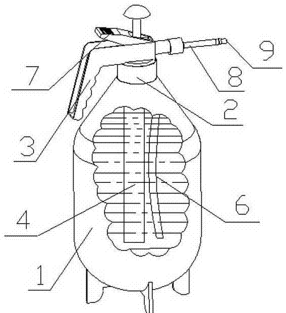
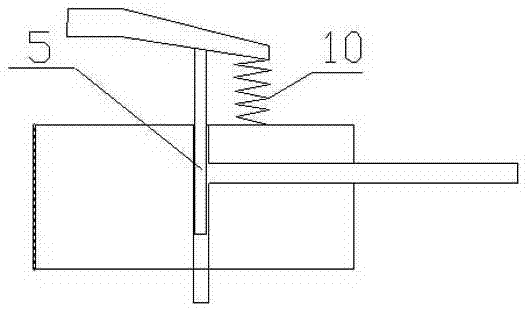
[0010] Such as figure 1 As shown, it is composed of liquid barrel 1, liquid barrel cover 2, handle 3, manual air pump 4, water outlet valve 5, water suction pipe 6, pressure rod 7, water spray rod 8 and nozzle 9, and liquid barrel cover 2 is installed on the liquid barrel 1 the top, the handle 3 is installed on the liquid tank cover 2, the manual air pump 4 is installed on the liquid tank cover 2, the air outlet of the manual air pump 4 communicates with the inside of the liquid tank 1, the water outlet valve 5 is installed in the pipe of the water suction pipe 6, and the water outlet The top of the valve 5 is not connected to the ground of the pressure bar 7, and is installed on the liquid bucket cover 2. The water inlet of the water suction pipe 6 communicates with the liquid bucket 1, and the water outlet of the water suction pipe 6 communicates with the water inlet of the water spray bar 8. Bar 7 is installed on the bung 2, and water spray bar 8 is installed on the bung 2,...


PUM


Abstract

The invention discloses a handheld compression sprayer. The handheld compression sprayer is composed of a liquid bucket (1), a liquid bucket cover (2), a handle (3), a manual blast pump (4), a water outlet valve (5), a water suction pipe (6), a pressing rod (7), a water spray rod (8) and a spray head (9). The handheld compression sprayer has the advantages of being capable of saving time and labor, fine and uniform in sprayed liquid, convenient to use and reasonable in design.

Description

technical field [0001] The invention relates to the field of compressed nebulizers. Background technique [0002] At present, there is no sprayer that can be compressed by hand. Contents of the invention [0003] The object of the present invention is to provide a hand-held compressed sprayer for the lack of a hand-held compressed sprayer. [0004] The invention consists of a liquid bucket, a liquid bucket cover, a handle, a manual air pump, a water outlet valve, a water suction pipe, a pressure rod, a water spray rod and a nozzle. The liquid bucket cover is installed on the top of the liquid bucket, and the handle is installed on the liquid bucket cover. The air pump is installed on the liquid barrel cover, the air outlet of the manual air pump communicates with the inside of the liquid barrel, the water outlet valve is installed in the pipe of the water suction pipe, the top of the water outlet valve is not connected to the pressure rod 7, and is installed on the liquid...

Claims


Application Information

Patent Timeline
IPC IPC(8): B05B11/00
CPCB05B11/1039B05B11/1042
Inventor 付安丽
Owner 付安丽
Why Eureka
Try Eureka