A lever mechanism for a book-turning machine

A lever and book machine technology, applied in the field of book turning machines, can solve the problems of reducing people's reading speed and wasting reading time, so as to reduce the time for turning pages and improve work efficiency

Active Publication Date: 2018-05-11
NINGBO UNIVERSITY OF TECHNOLOGY
View PDF6 Cites 0 Cited by
  • Summary
  • Abstract
  • Description
  • Claims
  • Application Information

AI Technical Summary

Problems solved by technology

[0002] The book-turning machine can help people to turn the pages of the paper on the book, so that people can read the book conveniently. Thus, the page-turning mechanism of the book-turning machine is very important to the book-turning machine. In the prior art Among them, for example, the publication number is the page-turning device of the automatic book-turning machine of CN103029481A, which includes a guide rod, a slide block, a wire rope, a fixed pulley, a wire reel, a page-turning stick and a book-turning machine frame body, and the slide block is slidably connected with the guide rod , the fixed pulley and the wire reel are respectively fixed on the book-turning frame body, the wire rope is wound between the fixed pulley and the wire reel, the page-turning rod is fixedly connected to the slider, and the slider is fixedly connected to the wire rope, although the page-turning device can The page-turning function of the book-turning machine is realized, but its slider is slidably connected to the guide rod, and the page-turning rod is fixedly connected to the slider. When the page-turning rod of the page-turning device turns the book once, the slider needs to Only by sliding back and forth on the guide bar can the pages of the book be turned, so, for some people with fast reading speed, the page turning mechanism will waste a lot of reading time and reduce people's reading speed

Method used


Image

  • A lever mechanism for a book-turning machine
  • A lever mechanism for a book-turning machine
  • A lever mechanism for a book-turning machine

Examples


Embodiment Construction

[0026] The following are specific embodiments of the present invention and in conjunction with the accompanying drawings, the technical solutions of the present invention are further described, but the present invention is not limited to these embodiments.

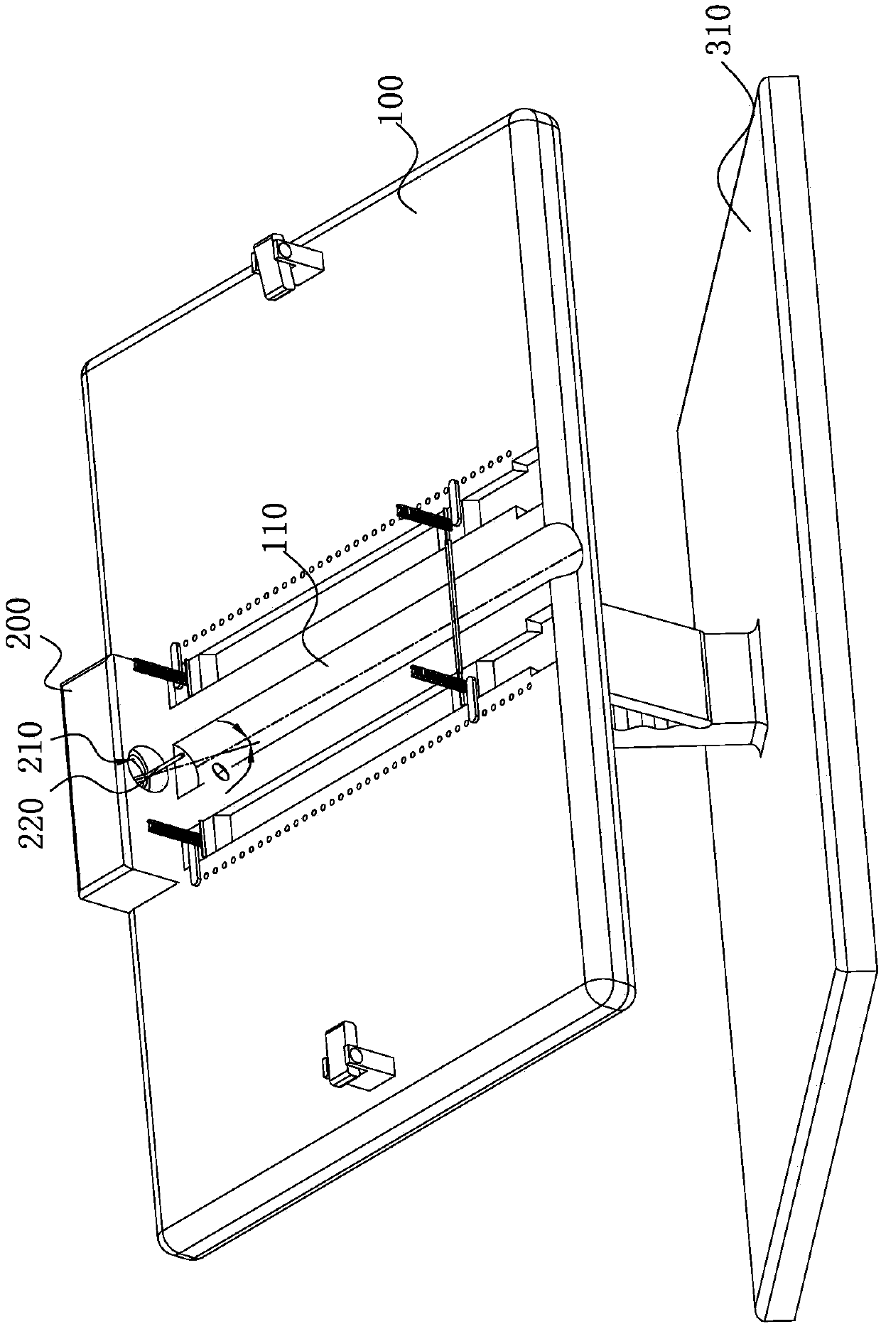
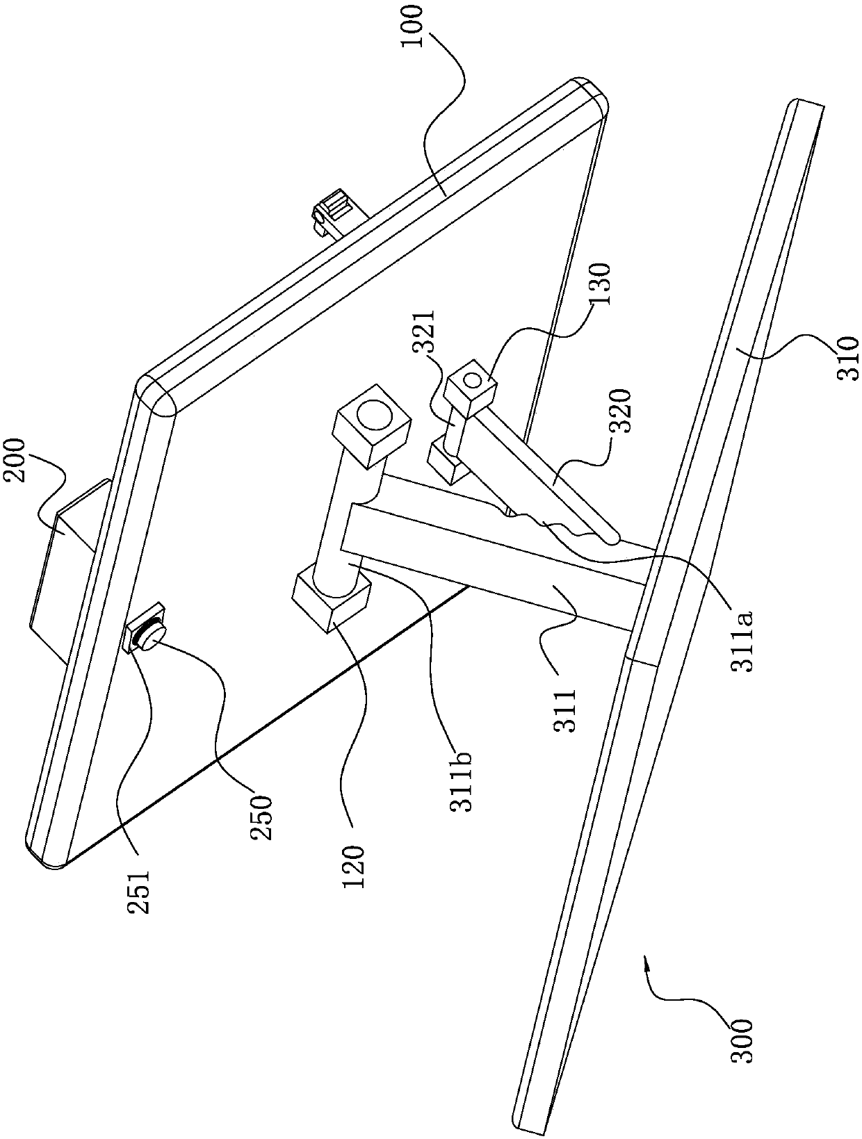
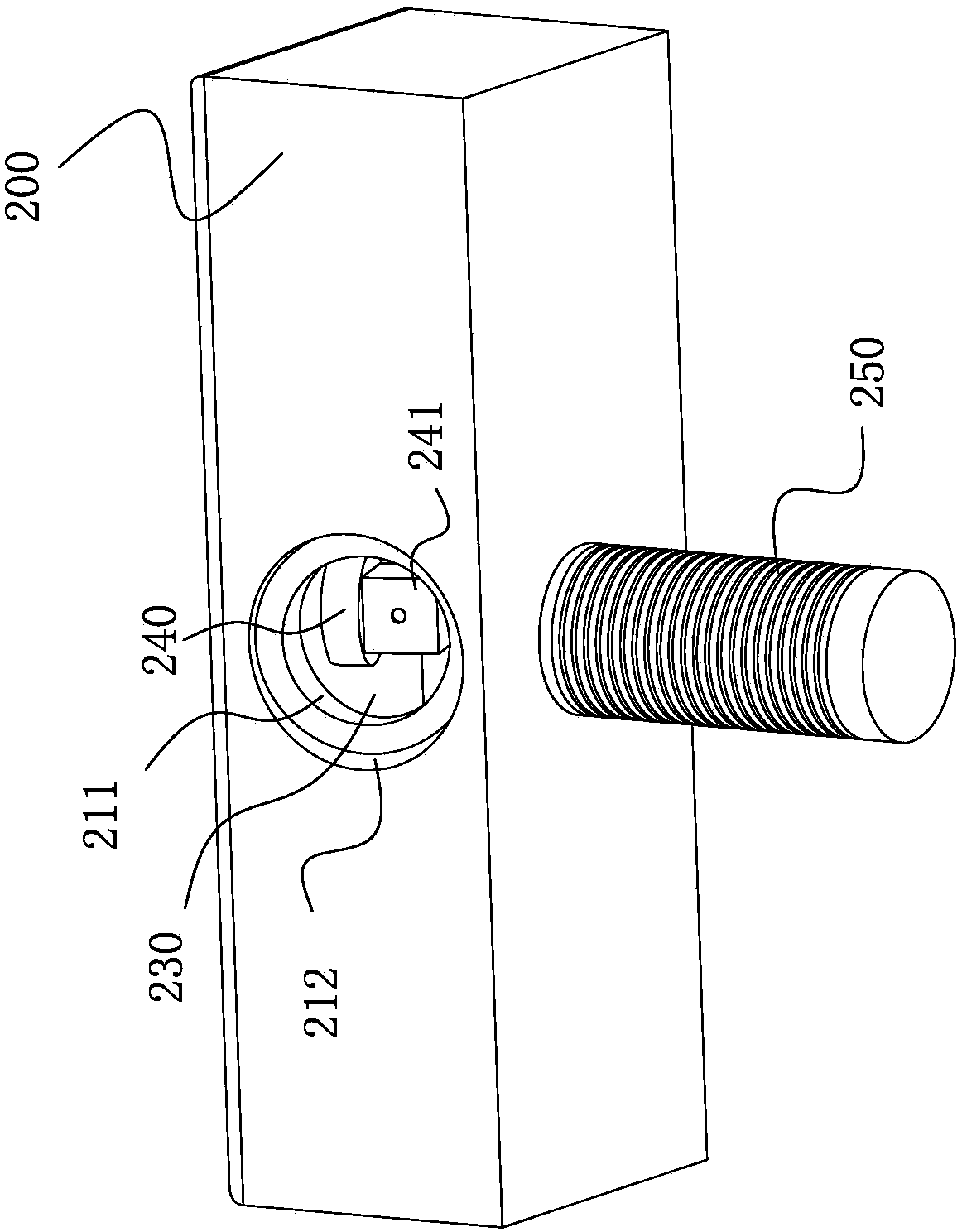
[0027] Such as Figure 1-Figure 6 As shown, a lever mechanism for a book turning machine according to the present invention includes a placement frame 100 , a support mechanism 300 , a housing 200 , a guide hole 210 and a lever 220 .

[0028] Further, one side of the display frame 100 is provided with a support mechanism 300 for adjusting the angle of the display frame 100; the housing 200 is detachably connected to one end of the other side of the display frame 100, and can move relative to the display frame 100. A guide hole 210 is opened on one side of the housing 200, and the central axis of the guide hole 210 intersects with the display rack 100 and forms an acute angle θ; When working, the side of the driving rod 22...


PUM


Abstract

The invention provides a lifting rod mechanism for a page turning machine, and belongs to the technical field of page turning machines. The lifting rod mechanism solves the problems that an existing page turning machine is low in page turning efficiency and not convenient to use. The lifting rod mechanism for the page turning machine comprises a placing frame, a supporting mechanism, a shell, a guiding hole and a lifting rod. The guiding hole is in an oval shape, so that a track hole and a safety hole are both in an oval shape, the side face of a rotation rod can move along the side face of the track hole, the page turning rod is fixedly connected with the rotation rod, the center axis of the rotation rod is parallel to the placing frame, and accordingly when the rotation rod moves to the top end of the track hole, the page turning rod can be inserted in a book; and when the rotation rod moves to one end of a long axis of the track hole, the page turning rod can turn the page of the book; in addition, through the arrangement of the mechanism, book page turning can be achieved, meanwhile, the time for book page turning through the page turning machine can be greatly shortened, and the work efficiency of the lifting rod mechanism is improved.

Description

technical field [0001] The invention belongs to the technical field of book-turning machines, and relates to a lever mechanism, in particular to a lever mechanism for a book-turning machine. Background technique [0002] The book-turning machine can help people to turn the pages of the paper on the book, so that people can read the book conveniently. Thus, the page-turning mechanism of the book-turning machine is very important to the book-turning machine. In the prior art Among them, for example, the publication number is the page-turning device of the automatic book-turning machine of CN103029481A, which includes a guide rod, a slide block, a wire rope, a fixed pulley, a wire reel, a page-turning stick and a book-turning machine frame body, and the slide block is slidably connected with the guide rod , the fixed pulley and the wire reel are respectively fixed on the book-turning frame body, the wire rope is wound between the fixed pulley and the wire reel, the page-turning...

Claims


Application Information

Patent Timeline
Patent Type & Authority Patents(China)
IPC IPC(8): B42D9/08
CPCB42D9/08
Inventor 刘锡宁李佳焕马贞帅陈晓平
Owner NINGBO UNIVERSITY OF TECHNOLOGY
Why Eureka
Try Eureka