Stainless steel pipe conveying and rotating mechanism

A technology of rotating mechanism and steel pipe transportation, which is applied in the direction of conveyors, conveyor objects, transportation and packaging, etc. It can solve the problems of changing to the longitudinal state, the stainless steel pipe cannot achieve the horizontal state, and the poor effect, so as to meet the transportation requirements.

Inactive Publication Date: 2017-06-20
SUZHOU LIAORUO ELECTROMECHANICAL TECH CO LTD
View PDF0 Cites 7 Cited by
  • Summary
  • Abstract
  • Description
  • Claims
  • Application Information

AI Technical Summary

Problems solved by technology

[0004] When the existing stainless steel pipes are processed and transported, they are generally carried by conveyor belts or manually. When the conveyor belt is transported, the stainless steel pipes cannot be changed from the horizontal state to the vertical state, etc., which cannot meet the transportation requirements, and can only be transported manually. To achieve this effect, its efficiency is low and the effect is poor

Method used


Image

  • Stainless steel pipe conveying and rotating mechanism
  • Stainless steel pipe conveying and rotating mechanism
  • Stainless steel pipe conveying and rotating mechanism

Examples


Embodiment Construction

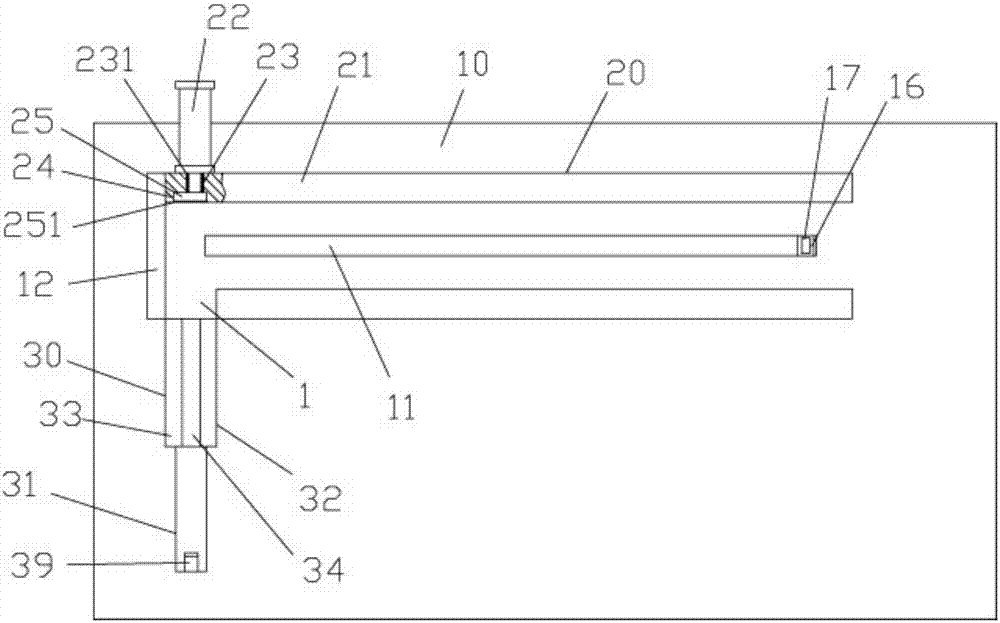
[0024] Examples, see e.g. Figure 1 to Figure 3 As shown, a stainless steel pipe conveying rotary mechanism includes a frame 10, the rear portion of the top surface of the top plate of the frame 10 is fixed with a transverse conveying mechanism 20, and the left side of the top surface of the frame 10 is fixed with a Longitudinal conveying rotation mechanism 30;

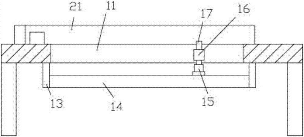
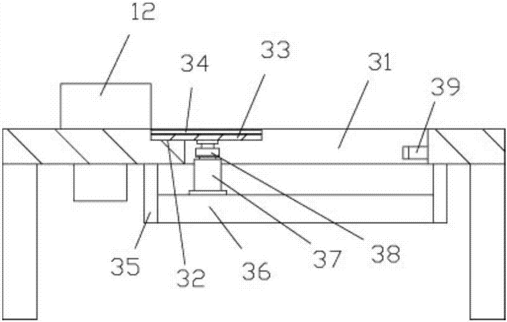
[0025] Described transverse conveying mechanism 20 comprises two mutually parallel transverse baffles 21 that are fixed on the top surface rear portion of the top plate of frame 10, between two transverse baffles 21 is conveying groove, between two transverse baffles 21 The top plate of the frame 10 is formed with a laterally moving through groove 11, the side baffle 12 is fixed on the top surface of the top plate of the frame 10, and the right rear part of the side baffle 12 is fixed on the rear transverse baffle 21, A discharge port 1 is formed between the front horizontal baffle 21 and the side baffle 12;

[0026...


PUM


Abstract

The invention discloses a stainless steel pipe conveying rotary mechanism, which comprises a frame, a transverse conveying mechanism is fixed on the rear of the top surface of the top plate of the frame, and a longitudinal conveying rotating mechanism is fixed on the left side of the top surface of the frame. Mechanism; the horizontal conveying mechanism includes two horizontal baffles parallel to each other fixed on the top rear of the top plate of the frame, between the two horizontal baffles is a conveying trough, and the frame between the two horizontal baffles The top plate of the frame is formed with a transverse moving channel, the side baffle is fixed on the top surface of the top plate of the rack, the right rear part of the side baffle is fixed on the rear horizontal baffle, the front horizontal line baffle and the side baffle There is a discharge port formed between the plates; it can automatically rotate while the stainless steel pipe is being conveyed, thereby changing the conveying state of the stainless steel pipe to meet the conveying requirements.

Description

[0001] Technical field: [0002] The invention relates to the technical field of stainless steel product processing, and more specifically relates to a stainless steel pipe conveying rotary mechanism. [0003] Background technique: [0004] When the existing stainless steel pipes are processed and transported, they are generally carried by conveyor belts or manually. When the conveyor belt is transported, the stainless steel pipes cannot be changed from the horizontal state to the vertical state, etc., which cannot meet the transportation requirements, and can only be transported manually. Reach this effect, its efficiency is low, and effect is poor. [0005] Invention content: [0006] The purpose of the present invention is to overcome the deficiencies of the prior art, and provide a stainless steel pipe conveying rotary mechanism, which can automatically rotate while the stainless steel pipe is being conveyed, thereby changing the conveying state of the stainless steel pipe...

Claims


Application Information

Patent Timeline
Patent Type & Authority Applications(China)
IPC IPC(8): B65G47/24
CPCB65G47/24B65G2201/0276
Inventor 陈玉燕
Owner SUZHOU LIAORUO ELECTROMECHANICAL TECH CO LTD
Why Eureka
Try Eureka