Multi-direction heavy-load conveyor and conveying method thereof

A technology of conveyors and conveyor lines, which is applied in the direction of conveyors, conveyor objects, transportation and packaging, etc., which can solve the problems of increasing the process of adjusting the position of objects, increasing the difficulty of positioning, and rushing out of objects, so as to reduce adjustment or positioning Difficulty, simple structure, exquisite design effect

Pending Publication Date: 2019-09-13
SUZHOU HONBEST CLEAN TECH CO LTD
View PDF0 Cites 4 Cited by
  • Summary
  • Abstract
  • Description
  • Claims
  • Application Information

AI Technical Summary

Problems solved by technology

[0005] 1. It can only be transferred in one direction, and cannot be transferred in two directions;
[0006] 2. When items are transferred from one conveyor line to another, the speed of item transfer should not be too fast, otherwise the items may rush out of another conveyor line, reducing safety. At the same time, items are transferred to another conveyor line. The position on a conveyor line cannot guarantee consistency, which increases the process of adjusting the position of subsequent items or increases the difficulty of subsequent positioning
[0007] In addition, for the transportation of some heavy items, the conventional belt conveyor line has poor load-bearing performance and relatively poor transportation stability. Although the conventional roller conveyor line has good weighing performance, it needs to go through complicated The transmission structure is used to realize the drive of the roller, and the structure is relatively complicated

Method used


Image

  • Multi-direction heavy-load conveyor and conveying method thereof
  • Multi-direction heavy-load conveyor and conveying method thereof
  • Multi-direction heavy-load conveyor and conveying method thereof

Examples


Embodiment Construction

[0044] Objects, advantages and features of the present invention will be illustrated and explained by the following non-limiting description of preferred embodiments. These embodiments are only typical examples of applying the technical solutions of the present invention, and all technical solutions formed by adopting equivalent replacements or equivalent transformations fall within the protection scope of the present invention.

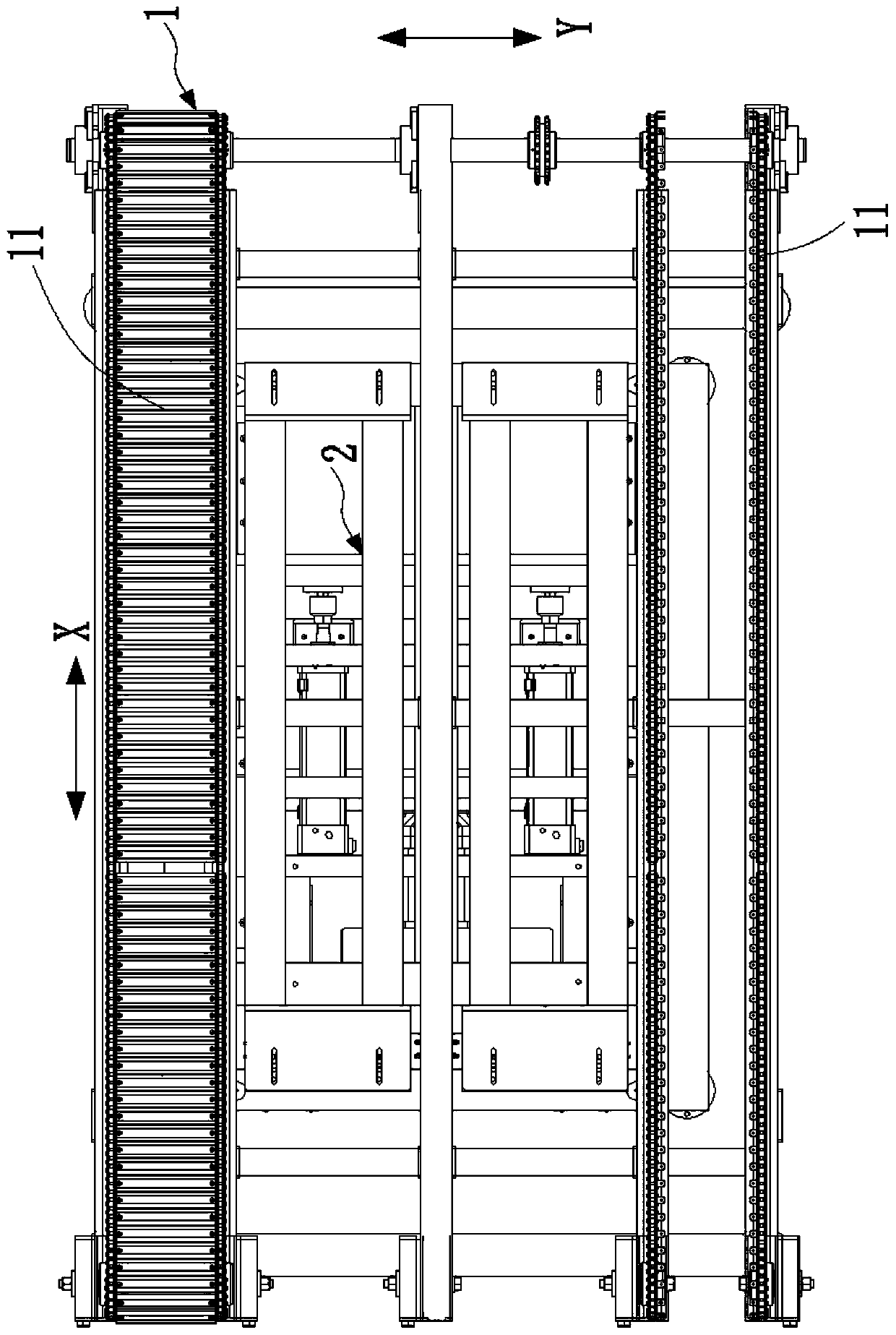
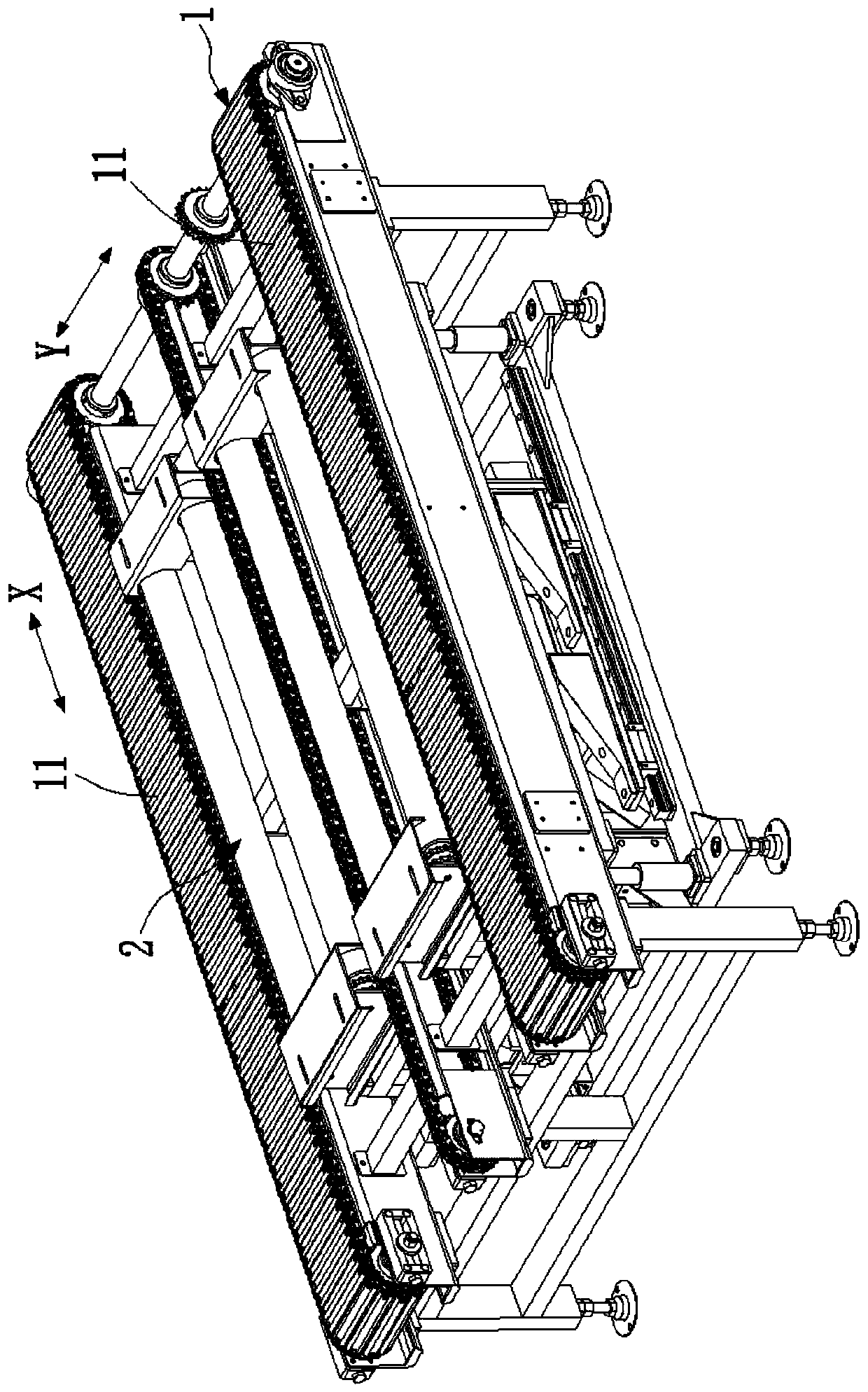
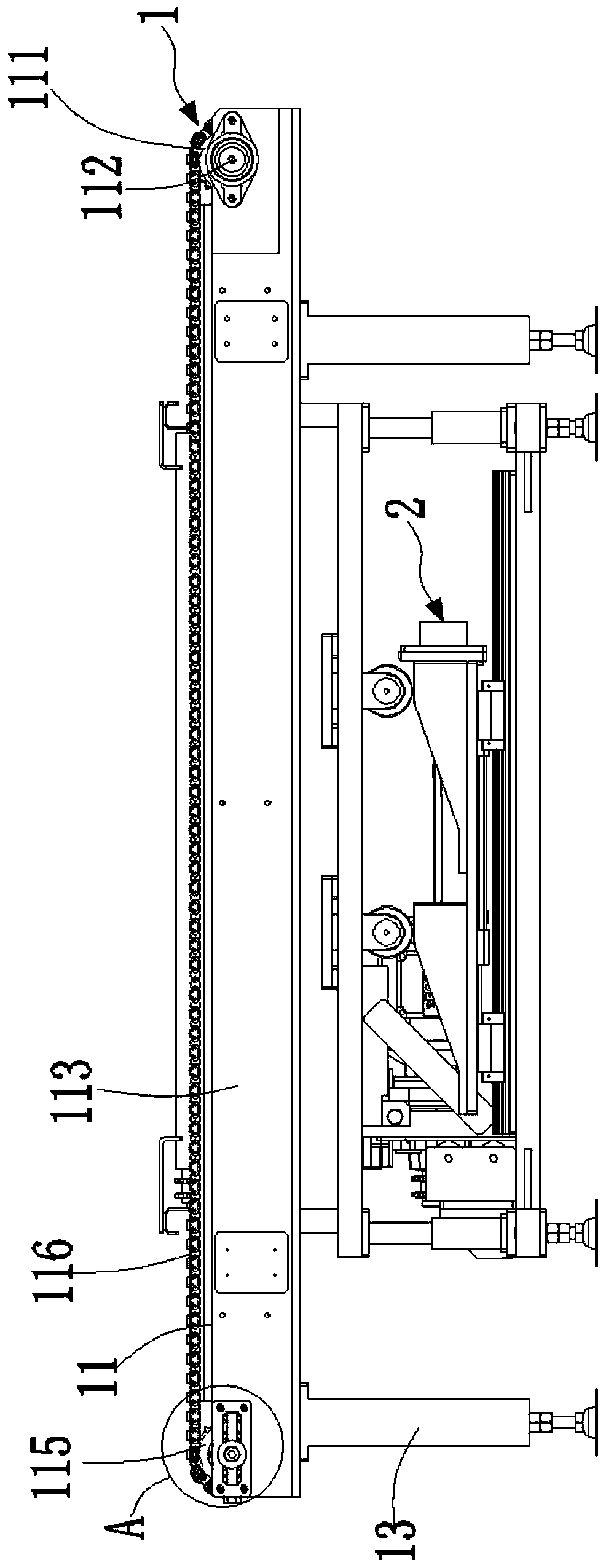
[0045] In the description of the scheme, it should be noted that the terms "center", "upper", "lower", "left", "right", "front", "rear", "vertical", "horizontal", " The orientation or positional relationship indicated by "inner", "outer", etc. is based on the orientation or positional relationship shown in the drawings, and is only for the convenience of description and simplification of description, rather than indicating or implying that the device or element referred to must have a specific orientation , constructed and operated in a particular or...


PUM


Abstract

The invention discloses a multi-direction heavy-load conveyor and a conveying method thereof. The multi-direction heavy-load conveyor comprises a first conveying line and a second conveying line, wherein the first conveying line carries out conveying in a first direction, and the second conveying line carries out conveying in a second direction perpendicular to the first direction, the first conveying line comprises two chain plate conveying belts, wherein the two conveying surfaces of the two chain plate conveying belts are equal in height and are arranged at an interval, the width of the chain plate conveying belts is smaller than 1 / 4 width of the conveying surface of the first conveying line, the second conveying line is located between the two chain plate conveying belts, and the conveying surface of the second conveying line and the conveying surface of the first conveying line have a height difference. According to the scheme, the second conveying line capable of ascending and descending is additionally arranged between the two chain plate conveying belts, and the width of the chain plate conveying belts is controlled, so that the bearing capacity of the first conveying lineis effectively guaranteed, the conveying requirement of large-weight articles is met, and the deformation risk of chain plates can be reduced, and meanwhile, the two conveying lines are different in conveying direction and have two position states, so that bidirectional transfer between the two conveying lines can be effectively realized.

Description

technical field [0001] The invention relates to the field of conveying equipment, in particular to a multi-directional heavy-duty conveyor and a conveying method thereof. Background technique [0002] With the rapid development of industrial automation, the transportation of various items in the process of enterprise production and logistics sorting is often realized by means of assembly lines. As a result, various conveyor line equipment has been developed and applied. [0003] In the actual conveying process, there are often situations where it is necessary to transfer items from one conveying line to another conveying line. [0004] Due to the structural limitations of the transmission conveyor line, it is impossible to realize the overlapping setting of the two conveyor lines. Therefore, the output end of one conveyor line can only be docked with the side of the other conveyor line to achieve load transfer. The problem with this structure is: [0005] 1. It can only be ...

Claims


Application Information

Patent Timeline
Patent Type & Authority Applications(China)
IPC IPC(8): B65G47/52B65G17/12
CPCB65G17/12B65G47/52
Inventor 陈建宝周飞
Owner SUZHOU HONBEST CLEAN TECH CO LTD
Why Eureka
Try Eureka