A fully automatic preheating furnace

A preheating furnace, fully automatic technology, used in furnaces, furnace types, lighting and heating equipment, etc., can solve the problems of inability to remove dust from the heating plate, deformation of the heating plate at the bottom, insufficient negative pressure, etc., to reduce cable breakage. Risk, stress reduction, effect of reducing temperature effects

Active Publication Date: 2021-03-12
深圳市鹏翔运达机械科技有限公司
View PDF10 Cites 3 Cited by
  • Summary
  • Abstract
  • Description
  • Claims
  • Application Information

AI Technical Summary

Problems solved by technology

[0002] At present, the battery contact preheating process in the industry mainly relies on the lifting mechanism to lift the heating plate-the loading and unloading module takes the discharge core-the heating plate is stacked and heated to achieve the purpose of preheating the battery, and the front end of the air claw is equipped with a dust removal air knife Regularly remove dust from the heating plate; however, when lifting the bottom heating plate, it is necessary to lift all the heating plates above, resulting in greater force on the bottom heating plate, deformation of the bottom heating plate, and greater resistance between the guide rods when lifting , prone to failure; in addition, during the lifting process of the heating plate, because the heating plate cable is not fixed well, the frequency of use is too high, which will lead to bad problems such as cable breakage; once the transmission mechanism of the heating plate group fails, other heating The board cannot output the internally baked cells; the dust removal by the air knife is 20mm away from the surface of the heating board, resulting in insufficient negative pressure, which cannot perfectly remove dust from the heating board

Method used


Image

  • A fully automatic preheating furnace
  • A fully automatic preheating furnace
  • A fully automatic preheating furnace

Examples


Embodiment Construction

[0040] The present invention will be further described below in conjunction with specific drawings and embodiments.

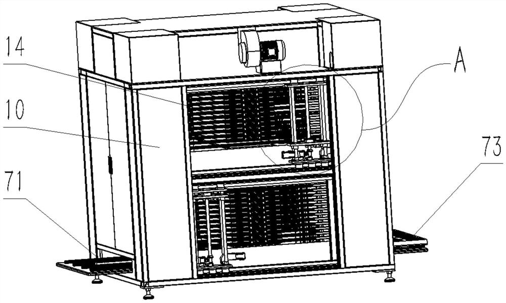
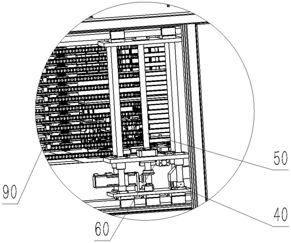
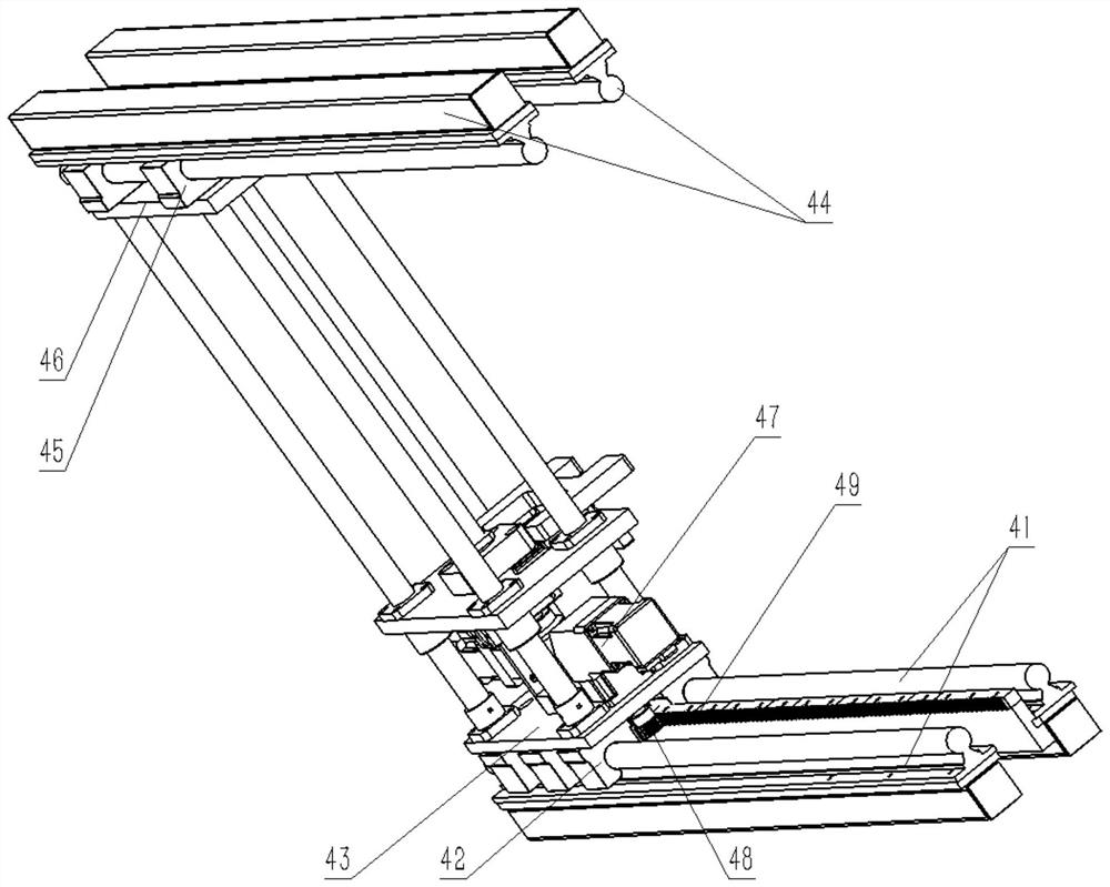
[0041] combine Figure 1-16 , the present invention provides a fully automatic preheating furnace, comprising a furnace body frame 10, a battery loading station 11, a battery heating station 12 and a battery unloading station 13, a heating chamber 14 is provided in the furnace body, and a battery heating station 12 is located in the heating chamber 14, the battery loading station 11 is located in the front of the battery heating station 12, the battery unloading station 13 is located in the rear of the battery heating station 12, and several layers of trays are arranged in the heating chamber 14. The heating plate 20, the tray-type heating plate 20 is horizontally movable and fixed in the furnace body frame 10 through the heating plate guide assembly 30, and it also includes pushing the tray-type heating plate 20 to move back and forth to the battery feeding st...


PUM


Abstract

The invention provides a fully automatic preheating furnace, comprising a furnace body frame, a battery loading station, a battery heating station and a battery unloading station, the battery heating station is located in a heating chamber of the furnace body frame, and the heating chamber Several layers of tray-type heating plates are set up and down in sequence. The tray-type heating plates can be horizontally moved and fixed in the furnace body frame through the heating plate guide assembly. It also includes pushing the tray-type heating plates to move back and forth to heat the battery at the charging station and battery. The heating plate toggle device for switching between the station and the battery unloading station. The invention adopts a tray-type heating plate that can be pushed out horizontally, which does not need to carry the gravity of the combination of heating plate groups, and reduces the deformation of the heating plate. Drag chains can be installed on both sides of the tray-type heating plate that can be pushed out horizontally to prevent cables and air pipes from moving. When breakage occurs, the tray-type heating plate is equipped with a dust removal negative pressure tube to increase the distance between the dust and the dust removal tube and increase the dust removal effect.

Description

technical field [0001] The invention relates to the technical field of lithium battery production equipment, in particular to a fully automatic preheating furnace. Background technique [0002] At present, the battery contact preheating process in the industry mainly relies on the lifting mechanism to lift the heating plate-the loading and unloading module takes the discharge core-the heating plate is stacked and heated to achieve the purpose of preheating the battery, and the front end of the air claw is equipped with a dust removal air knife Regularly remove dust from the heating plate; however, when lifting the bottom heating plate, it is necessary to lift all the heating plates above, resulting in greater force on the bottom heating plate, deformation of the bottom heating plate, and greater resistance between the guide rods when lifting , prone to failure; in addition, during the lifting process of the heating plate, because the heating plate cable is not fixed well, th...

Claims


Application Information

Patent Timeline
Patent Type & Authority Patents(China)
IPC IPC(8): F27B17/00H01M10/058
CPCF27B17/0016H01M10/058Y02E60/10Y02P70/50
Inventor 陈磐崔帅团童金顺
Owner 深圳市鹏翔运达机械科技有限公司
Why Eureka
Try Eureka