Dual-core visual inspection buckling restraint support

A technology of buckling restraint and restraint plate, which is applied to building components, earthquake resistance, building types, etc., can solve the problems of reducing the overall stiffness of restraining components, destroying the main body of the structure, increasing the difficulty and cost of post-earthquake repair, and improving low-cycle fatigue performance. , The effect of improving low cycle fatigue performance and reducing surface strain

Active Publication Date: 2017-06-20
SOUTHEAST UNIV
View PDF10 Cites 9 Cited by
  • Summary
  • Abstract
  • Description
  • Claims
  • Application Information

AI Technical Summary

Problems solved by technology

[0002] Before the 1990s, the traditional anti-seismic method used to dissipate the seismic energy through the local yield of the main structure, such as the beam-hinge mechanism. Conducive to post-earthquake repair of structures
The buckling restraint support of the all-steel peripheral restraint section is adopted, such as the public patent CN101974947B or CN101718123B, the core member of which is a steel member such as I-shaped steel, and the flange and web of the I-shaped section are restrained by the peripheral all-steel restraint member at the same time. The connection welds or chamfers between the flange and the web of the profiled section conflict with the peripheral constraining members, mak

Method used


Image

  • Dual-core visual inspection buckling restraint support
  • Dual-core visual inspection buckling restraint support
  • Dual-core visual inspection buckling restraint support

Examples


Embodiment 1

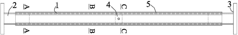
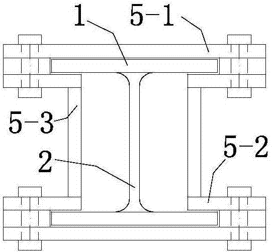
[0036] Such as Figure 1~7 Shown: a dual-core visual inspection buckling restraint support, including two energy-dissipating inner core plates 1, two sets of end stiffening plates 2, two end connecting plates 3, a connecting positioning plate 4 and a peripheral restraining component 5; Two energy-dissipating inner core plates 1 are placed in parallel along the thickness direction; the end stiffening plate 2 is a rectangular plate, and the two opposite sides of the end stiffening plate 2 are vertically fixed to the inner side of the parallel energy-dissipating inner core plate 1 as a cross section For the web, the other side of the end stiffening plate 2 is in the same plane as the end edge of the energy dissipating inner core plate 1; the end connecting plate 3 is connected to the end edges of the two energy dissipating inner core plates 1 and the end stiffening plate 2 One side is fixed; the connecting positioning plate 4 is also a rectangular plate, and the two opposite sides...

Embodiment 2

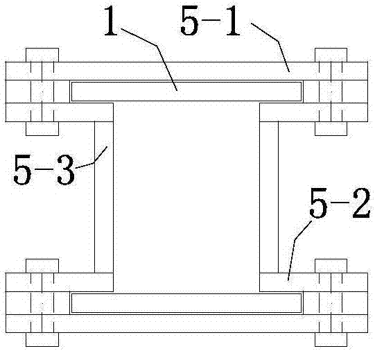
[0038] Such as Figure 8 Shown: this embodiment is the same as the rest of the embodiment 1, the difference is that the constraining plate 5-1 is a channel steel, and the inner side of the web is constrained close to the energy dissipating inner core plate 1, and two partial constraining plates 5-2 It forms a groove weld with the connecting plate 5-3.

Embodiment 3

[0040] Such as Picture 9 Shown: this embodiment is the same as the rest of the embodiment 1, the difference is that the energy-consuming inner core plate 1 is narrow in the middle and wide on both sides.


PUM


Abstract

The invention discloses a dual-core visual inspection buckling restraint support. The dual-core visual inspection buckling restraint support comprises two energy consumption inner core panels, two sets of end stiffening plates, two end connecting plates, a plurality of sets of connecting positioning plates and a peripheral restraint component; the two energy consumption inner core panels are arranged in parallel in the panel thickness direction, the end stiffening plates are rectangular plates, the two opposite sides of each set of end stiffening plates are perpendicularly and fixedly connected with the parallelly-arranged energy consumption inner core panels, and the other sides of the end stiffening plates and the end sides of the energy consumption inner core panels are located in the same plane; the end connecting plates are fixedly connected with the end sides of the two energy consumption inner core panels and one sides of the end stiffening plates; and the connecting positioning plates are also rectangular plates, in the parallelly-arranged energy consumption inner core panels, the two opposite sides of the connecting positioning plates are perpendicularly and fixedly connected with the energy consumption inner core panels, and all the connecting positioning plates are located in the same plane and distributed at equal intervals.

Description

Technical field [0001] The invention belongs to the field of civil engineering and relates to a buckling restraint support for reducing the seismic response of an engineering structure. Background technique [0002] Before the 1990s, the traditional method of structural seismic resistance was to dissipate seismic energy through local yielding of the main structure, such as beam hinge mechanism. This seismic energy dissipation method caused damage to the main structure of the structure, which seriously increased the difficulty and cost of post-earthquake repair. Conducive to the post-earthquake repair of the structure. Since the Hanshin Earthquake in Japan and the Northridge Earthquake in the United States, the buckling restraint brace has been rapidly promoted and applied in developed countries such as Japan and the United States as an energy-dissipating component with superior performance, and research in my country is also under development. stage. The buckling restraint suppo...

Claims


Application Information

Patent Timeline
IPC IPC(8): E04B1/98E04H9/02
CPCE04H9/021
Inventor 王春林刘烨
Owner SOUTHEAST UNIV
Why Eureka
Try Eureka