Linkage monitoring method and device of dome camera

A ball camera and linkage technology, applied in the direction of TV, closed-circuit television system, electrical components, etc., can solve the problem of missing video recording and observation of emergency scene, and achieve the effect of comprehensive and reliable event information

Inactive Publication Date: 2017-06-20
SHANGHAI LINGSHI COMM TECH DEV
View PDF14 Cites 9 Cited by
  • Summary
  • Abstract
  • Description
  • Claims
  • Application Information

AI Technical Summary

Problems solved by technology

[0004] Therefore, the technical problem to be solved by the present invention is that the existing high-altitude observation systems all use manual manual control of the high-altitude dome camera, which often misses the video recording and observation of the emergency scene due to the untimely response of the operator.

Method used


Image

  • Linkage monitoring method and device of dome camera
  • Linkage monitoring method and device of dome camera
  • Linkage monitoring method and device of dome camera

Examples


Embodiment 1

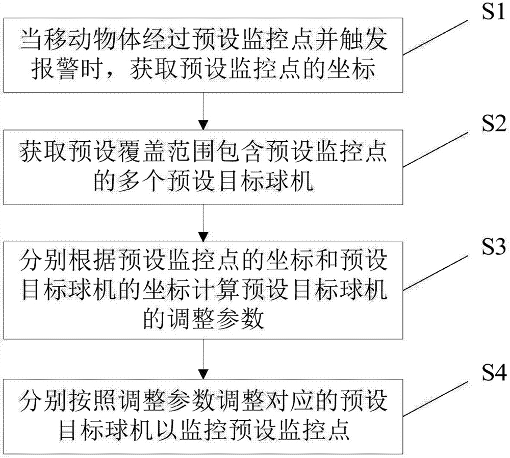
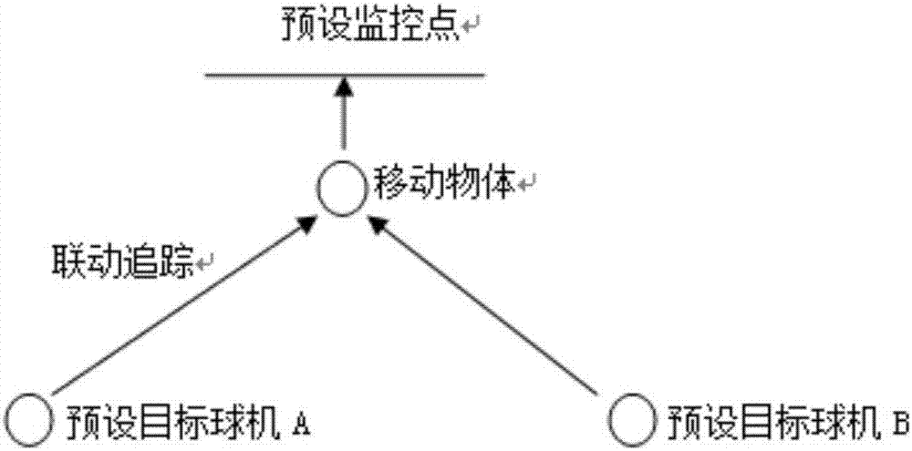
[0023] Such as figure 1 with 2 As shown, this embodiment provides a method for linkage monitoring of dome cameras. The method can form a linkage control between a high-altitude observation system composed of multiple preset dome cameras and a monitoring alarm system, including the following steps:

[0024] S1: When a moving object passes through a preset monitoring point and triggers an alarm, obtain the coordinates of the preset monitoring point. The preset monitoring point is set in the target monitoring area, and a monitoring alarm system is set at the preset monitoring point.

[0025] S2: Obtain multiple preset target dome cameras with preset coverage areas including preset monitoring points.

[0026] S3: Calculate the adjustment parameters of the preset target ball machine according to the coordinates of the preset monitoring point and the preset target ball machine respectively.

[0027] S4: Adjust the corresponding preset target dome camera according to the adjustment parameter...

Embodiment 2

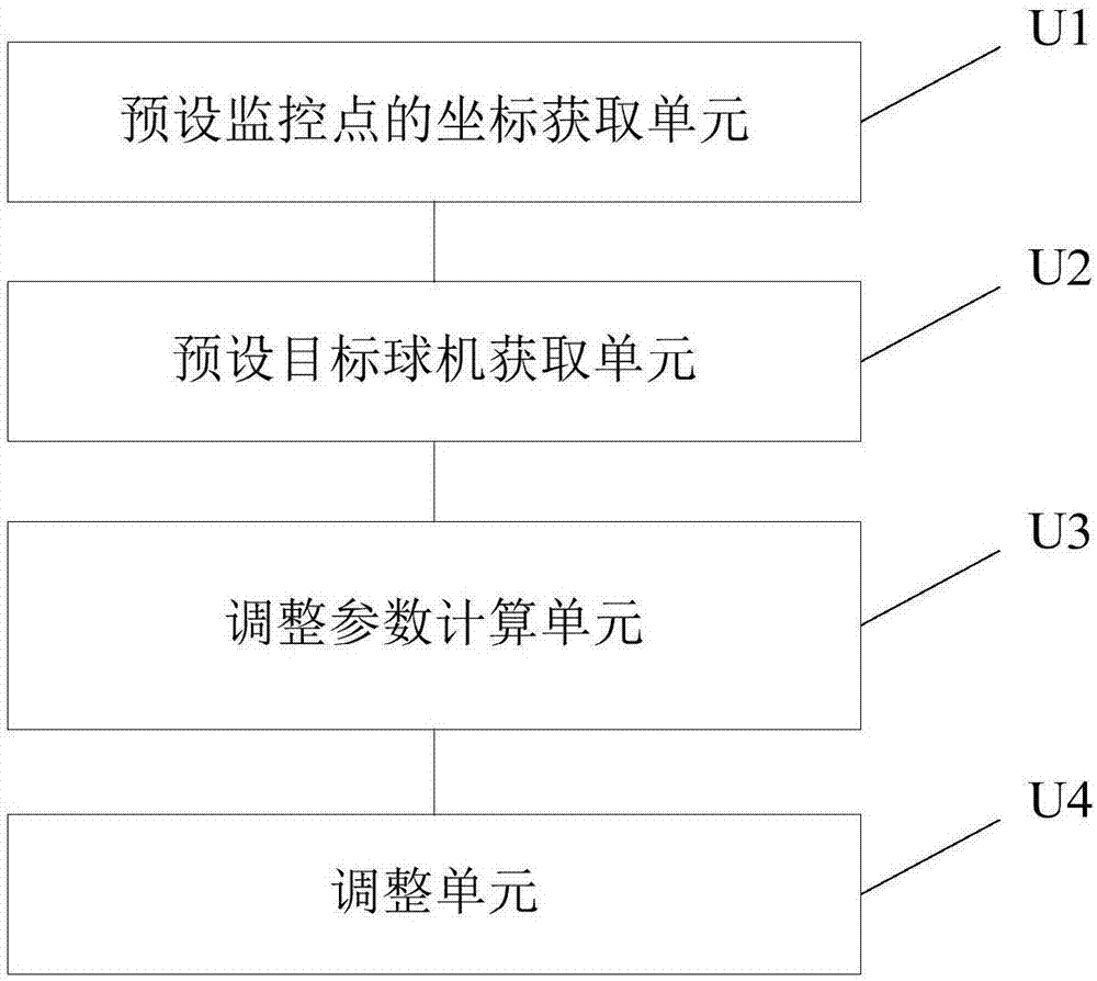
[0043] Such as image 3 As shown, this embodiment provides a dome camera linkage monitoring device, including:

[0044] The coordinate acquisition unit U1 of the preset monitoring point is used to obtain the coordinates of the preset monitoring point when the moving object passes the preset monitoring point and triggers an alarm;

[0045] The preset target dome camera acquisition unit U2 is used to obtain a plurality of preset target dome cameras whose preset coverage includes preset monitoring points;

[0046] The adjustment parameter calculation unit U3 is used to calculate the adjustment parameters of the preset target ball machine according to the coordinates of the preset monitoring point and the coordinates of the preset target ball machine respectively;

[0047] The adjustment unit U4 adjusts the corresponding preset target dome camera according to the adjustment parameters to monitor the preset monitoring points.

[0048] In the method for linkage monitoring of dome cameras pro...


PUM


Abstract

The invention provides a linkage monitoring method and device of dome cameras, and relates to the video monitoring technology field. The method includes the following steps: obtaining a coordinate of a preset monitor point when a moving object passes by the preset monitor point and triggers alarming; obtaining multiple preset target dome cameras with a preset covering range containing the preset monitor point; calculating adjusting parameters of the preset target dome cameras on the basis of the coordinate of the preset monitor point and coordinates of the preset target dome cameras; and adjusting the corresponding preset target dome cameras on the basis of the adjusting parameters to monitor the preset monitor point. The coordinate of the preset monitor point and the coordinates of the preset dome cameras are known, so once a certain monitor point triggers alarming, the preset dome cameras can quickly and accurately lock the preset monitor point on the basis of the preset coordinate to record events occurring at the preset monitor point in real time. Moreover, multiple high-altitude dome cameras preset in advance can cover the preset monitor point, so events that occur can be recorded from many angles, and recorded event information is more comprehensive and reliable.

Description

Technical field [0001] The invention relates to the technical field of video monitoring, in particular to a method and device for linkage monitoring of dome cameras. Background technique [0002] In the current high-altitude observation system, the high-altitude dome cameras are installed evenly at some high places in the city, and the high-altitude dome cameras are controlled by the background. The user can move the high-altitude dome cameras up, down, left, and right through operations on the interface, and The distance is increased to realize the observation and monitoring of every corner of the city. [0003] However, this kind of high-altitude observation system has certain limitations. Because it is manually operated by the user, for some emergencies that require high real-time performance, the high-altitude dome camera cannot be quickly and accurately positioned due to the reaction time of the operator. The scene. Therefore, this kind of high-altitude observation system of...

Claims


Application Information

Patent Timeline
Patent Type & Authority Applications(China)
IPC IPC(8): H04N7/18
CPCH04N7/181
Inventor 崔中发潘洋柏亚运郭磊陈黎陈志权
Owner SHANGHAI LINGSHI COMM TECH DEV
Why Eureka
Try Eureka