
Laser processing apparatus

A laser processing and laser technology, applied in laser welding equipment, metal processing equipment, manufacturing tools, etc., can solve the problems of uneconomical and incomplete utilization, and achieve the effect of reducing costs

Inactive Publication Date: 2017-06-23
DISCO CORP
View PDF10 Cites 5 Cited by
  • Summary
  • Abstract
  • Description
  • Claims
  • Application Information

AI Technical Summary

Problems solved by technology

[0006] As mentioned above, the laser beam output from the laser oscillator used in the laser processing device is used after its output is adjusted to be low. For the output workpiece, more than 1 / 2 of the output of the laser beam emitted from the laser oscillator is discarded, and there is a problem that the capacity cannot be fully utilized and it is uneconomical.

Method used


Image

  • Laser processing apparatus
  • Laser processing apparatus
  • Laser processing apparatus

Examples


Embodiment Construction

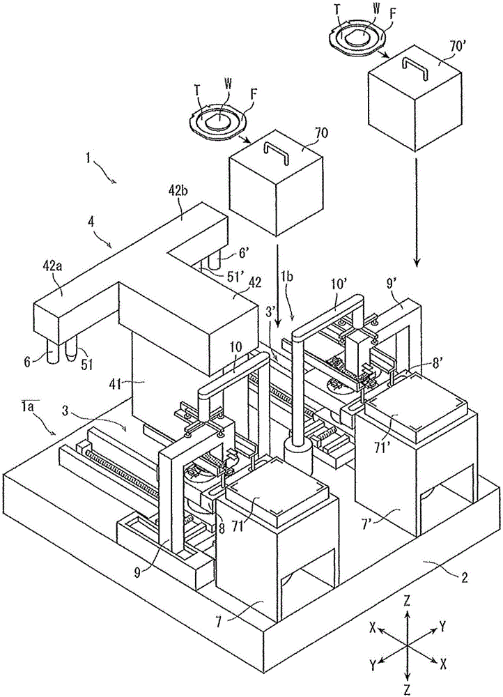
[0027] Hereinafter, preferred embodiments of the laser processing apparatus according to the present invention will be described in detail with reference to the drawings.

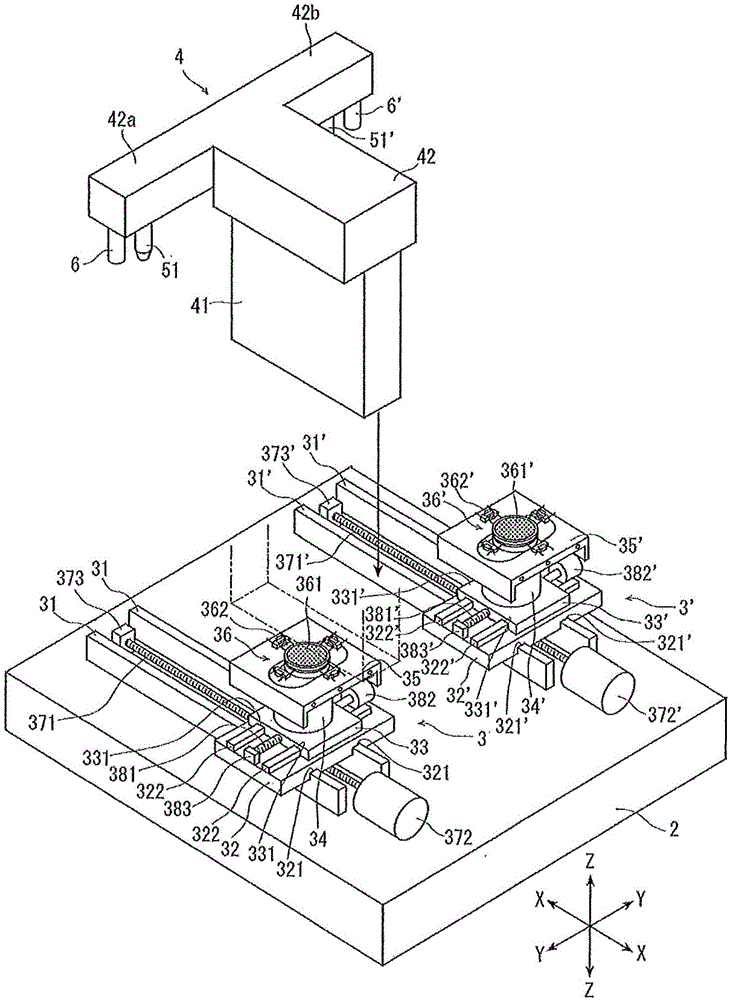
[0028] figure 1 An overall perspective view of the laser processing apparatus 1 of the present invention is shown in . figure 1 The laser processing device 1 shown has: a stationary base 2; a first chuck table mechanism 3, which is arranged on the stationary base 2 in a manner capable of moving in the X-axis direction indicated by an arrow X, and is mounted on the stationary base 2. The workpiece is held; the second chuck table mechanism 3', which is arranged in parallel with the first chuck table mechanism 3, is also arranged in a manner capable of moving in the X-axis direction, and the workpiece is processed. Hold; and the laser beam irradiation unit 4 as a laser beam irradiation member, which is arranged on the stationary base 2 in the region sandwiched between the first and second chuck table mechanis...


PUM


Abstract

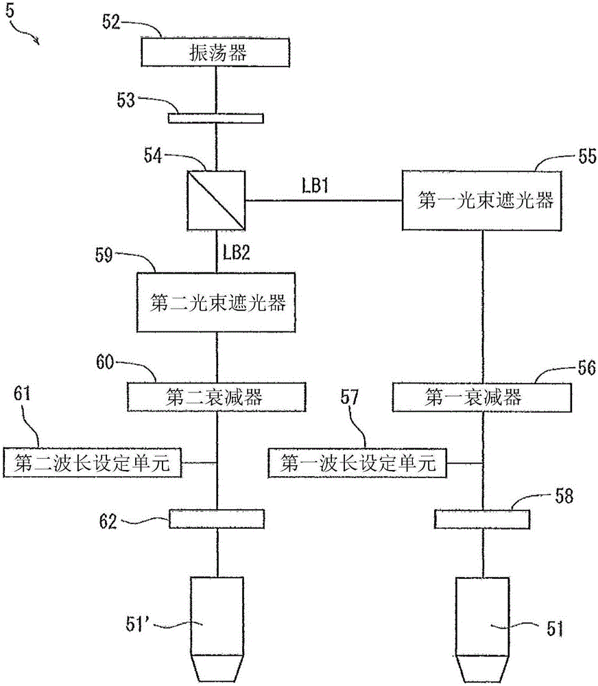
The invention discloses a laser processing apparatus which includes a first chuck table for holding a workpiece, a first X-axis moving unit for moving the first chuck table in the X direction, a first Y-axis moving unit for moving the first chuck table in the Y direction, and a first focusing unit for focusing a first laser beam to the workpiece which is held by the first chuck table, a second chuck table for holding a workpiece, a second X-axis moving unit for moving the second chuck table in the X direction, a second Y-axis moving unit which is in the Y direction which is perpendicular to the X direction, a second focusing unit which focuses a laser beam to the workpiece that is held by the second chuck table, a laser oscillator which produces a laser beam, and an optical system which branches the laser beam that is produced by the laser oscillator into . Other moving units move the second chuck table in the X direction and Y directions, and a second focusing unit focuses a second laser beam to the second workpiece. A laser oscillator produces an original laser beam, and an optical system branches the original laser beam into a first focusing unit and the second focusing unit.

Description

technical field [0001] The present invention relates to a laser processing device for processing a workpiece such as a semiconductor wafer by irradiating laser beams. Background technique [0002] In the process of manufacturing a semiconductor device using a laser processing apparatus, a plurality of regions are divided by dividing lines arranged in a grid on the front surface of a substantially disc-shaped semiconductor wafer, and ICs, ICs, etc. are formed in the divided regions. For devices such as LSI, the semiconductor wafer is cut by irradiating laser light along the planned division line, thereby dividing the region where the device is formed, and manufacturing individual semiconductor device chips. [0003] This laser processing device is known to be able to perform desired laser processing on a workpiece (for example, refer to Patent Document 1), and it includes: a chuck table that holds the workpiece; a laser beam irradiation member that holds the workpiece on the ...

Claims


Application Information

Patent Timeline
Patent Type & Authority Applications(China)
IPC IPC(8): B23K26/046B23K26/067B23K26/06H01L21/78
CPCB23K26/046B23K26/06B23K26/067H01L21/78B23K26/0676B23K26/0853B23K26/351B23K26/50B23K2103/56H01L21/6719H01L21/67346H01L21/67778H01L21/68H01L21/68707H01L21/268H01L21/67715H01L21/6835H01L21/68785H01L21/76H01L21/67115H01L21/68714
Inventor 尾上若奈泽边大树野村洋志藤泽尚俊万波秀年田中康平
Owner DISCO CORP
Learn More