Convenient airing shelf

A convenient and drying rod technology, applied in the field of drying racks, can solve the problems of affecting the appearance, damage to decoration, inconvenience for people, etc., and achieve the effect of long use time and convenient storage

Inactive Publication Date: 2017-06-23
周良操
View PDF0 Cites 0 Cited by
  • Summary
  • Abstract
  • Description
  • Claims
  • Application Information

AI Technical Summary

Problems solved by technology

But there is no more convenient and reliable way to do it
If it is fixed on the wall, the original decoration will be damaged during installation, and it will also affect the appearance and bring inconvenience to people.

Method used


Image

  • Convenient airing shelf
  • Convenient airing shelf
  • Convenient airing shelf

Examples


Embodiment Construction

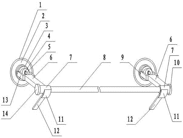
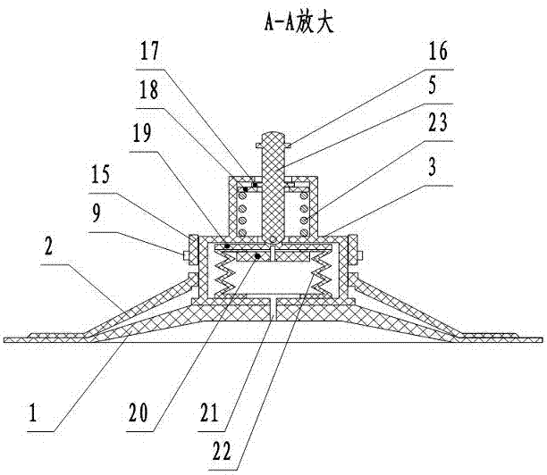
[0016] figure 1 In the middle is a three-dimensional view of the convenient use of the drying rack. Two suction cups have been adsorbed on the wall 24 . The suction cup shell 2 is pressed on the plastic disc 1 . The shell of the capsule dilator is referred to as the shell 3 hereinafter. The bottom of the shell 3 is a large shell, and the top is a small shell. The housing 3 is installed in the suction cup housing 2 . Drying bar cover 7, pull block 6, fork frame 13, spanner 15 are made into one, and spanner 15 is installed on the shaft pin 9 on the large housing. Also refer to Figure 4 , The airing rod cover 7 is provided with a stopper 11 for limiting the downward rotation angle of the bracket 12 and a bracket 25 connecting the bracket 12 . Bracket 12 is hinged on the support 25 on the airing pole cover 7, can rotate. Airing bar 8 one ends have airing bar head 14, and the other end has the plug head 10 that can cooperate with airing bar 8, prevents that airing bar comes ...


PUM


Abstract

Convenient drying rack, including drying rod, drying rod cover, plug head, support frame, trigger block, fork frame, suction cup, capsule expander. It can be easily adsorbed on the wall and hang towels and clothes on the glass. The capsule dilator housing consists of a small housing and a large housing. The airing rod cover, the wrench block, the fork frame and the wrench head are made into one, and are installed on the pivot pin of the large housing. A drying rod passes through the drying rod cover. The support bracket is hinged on the support on the drying rod cover. The large housing fits into the suction cup housing. A capsule and a lower pressing plate are installed in the large housing, and a benchmark, a clip spring and a pressing plate are installed in the small housing. The small hole communicates with the rubber disk in the capsule and the suction cup shell. The lower end of the pole is hinged with the lower pressure plate. The bottom plate of the large housing, the capsule and the rubber disc are integrated into one body. When in use, press the end of the pole and dial into the bayonet. Install the drying rod and the plug, press the suction cup on the wall, and turn the switch to be perpendicular to the wall. The end of the pole is dialed back to its original position. The rings of different colors on the small shell protruding from the pole can represent the vacuum degree in the plastic disc, reminding people when it is time to reinstall the suction cup.

Description

technical field [0001] The invention is a drying rack, in particular a convenient drying rack. Background technique [0002] Existing air racks are often screwed to hang towels, bath towels and the like on the walls of bedrooms or bathrooms, which are very inconvenient to install and cannot be moved after installation. If it is fixed with screws, it is necessary to drill holes on the wall, which is easy to drill and crack the wall tiles. It is very inconvenient to temporarily change the position of the fixed drying rack. Such as the side of the closet, the edge of the window sill, the window sill glass and other relatively convenient places, many people hope to have a hanging rack, which is convenient, does not cause damage to the original countertop, and can be quickly installed and removed. But there is no more convenient and reliable way to do it now. If it is fixed on the wall, the original decoration will be damaged during installation, and it will also affect the ap...

Claims


Application Information

Patent Timeline
Patent Type & Authority Applications(China)
IPC IPC(8): D06F57/12
CPCD06F57/12
Inventor 周良操
Owner 周良操
Why Eureka
Try Eureka