Vehicle-mounted lifting detecting device based on face recognition technology

A face recognition and detection device technology, applied in character and pattern recognition, instruments, closed-circuit television systems, etc., can solve problems such as being unable to move, public security officers unable to observe personnel at any time, and unable to uninstall at any time for viewing and maintenance.

Inactive Publication Date: 2017-06-23
ZHEJIANG UNIV OF TECH
View PDF10 Cites 7 Cited by
  • Summary
  • Abstract
  • Description
  • Claims
  • Application Information

AI Technical Summary

Problems solved by technology

[0002] Most of the current face cameras are fixed somewhere and cannot be moved, or installed at a high place and cannot be uninstalled at any time for viewing, maintenance, etc.
In addition, although we know that some key places are places where criminals often appear, such as stations, banks, parking lots, etc., the public security officers cannot observe the people entering and leaving dense crowds at any time, so as to achieve the attack on criminals in key places, and most of these key places Ordinary cameras are installed, even if they are not in all places as before, monitoring and shooting devices are installed in all places, there are many blind spots in perspective, in order to cope with the new public security situation, strengthen and innovate social management methods, we use technology and information Taking the construction as the carrier, taking the construction of urban monitoring and alarm networking system as the starting point, a vehicle-mounted lifting monitoring device based on face recognition technology is proposed, and the fixed monitoring deployment is converted into a mobile vehicle-mounted lifting monitoring device based on face recognition technology.

Method used


Image

  • Vehicle-mounted lifting detecting device based on face recognition technology
  • Vehicle-mounted lifting detecting device based on face recognition technology
  • Vehicle-mounted lifting detecting device based on face recognition technology

Examples


Embodiment Construction

[0023] The present invention will be described in further detail below in conjunction with the accompanying drawings.

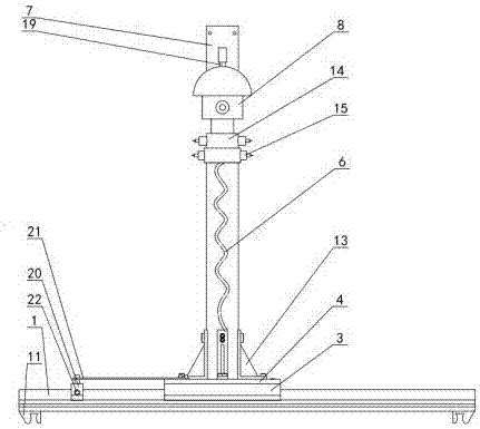
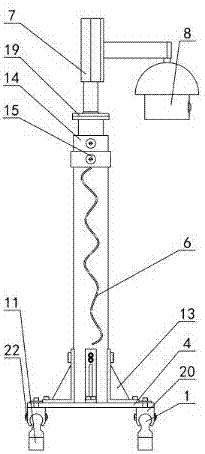
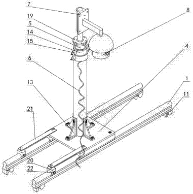
[0024] Such as Figure 1-11 As shown, the vehicle-mounted lifting detection device based on face recognition technology includes a slide rail 1, a fixing device 2, a large slider 3, a base 4, a manual lifting device 5, a spiral cable 6, a support plate 7, a face recognition camera 8, Display processor 9, car top 10, clamping device 11, car luggage rack 12, small support 13, joint sleeve 14, spring buckle 15, lock pin 16, spring 17, threaded hole 18, flange 19, small slide Block 20, connecting bar 21 and handle bolt 22. First, the slide rail 1 is placed horizontally on the roof 10 of the car. The two ends of the slide rail 1 are equipped with clamping devices 11. The clamping device 11 clamps the luggage rack 12 of the car to fix the slide rail 1 on the roof 10 of the car. The base 4 is fixed on the large slider 3, the manual lifting device 5 is fixedly conn...


PUM


Abstract

The invention discloses a vehicle-mounted lifting detecting device based on the face recognition technology. The vehicle-mounted lifting detecting device based on the face recognition technology comprises a sliding rail, a large sliding block matched with the sliding rail, a base fixed to the large sliding block and a manual lifting device fixed to the base. The two ends of the bottom of the sliding rail are fixedly provided with clamping devices. The portion, close to the base, of the sliding rail is provided with a fixing device used for fixing the base. A supporting plate is fixedly provided with a face recognition camera. A spiral cable is arranged in the manual lifting device. One end of the spiral cable is in circuit connection with the face recognition camera. The other end of the spiral cable is connected with a display processor. The vehicle-mounted lifting detecting device based on the face recognition technology has the beneficial effects that through the manual lifting device fixed to the base, the height of the monitoring device can be manually adjusted, the face recognition camera can achieve face monitoring and tracing in crowds, and the display processor processes and compares shooting data to find out a stated target.

Description

technical field [0001] The invention relates to the technical field of photographing detection devices, in particular to a vehicle-mounted lifting detection device based on face recognition technology. Background technique [0002] Most of the current face cameras are fixed somewhere and cannot be moved, or installed at a high place and cannot be uninstalled for viewing, maintenance, etc. at any time. In addition, although we know that some key places are places where criminals often appear, such as stations, banks, parking lots, etc., the public security officers cannot observe the people entering and leaving dense crowds at any time, so as to achieve the attack on criminals in key places, and most of these key places Ordinary cameras are installed, even if they are not in all places as before, surveillance cameras are installed in all places, and there are many blind spots of perspective. Taking the construction as the carrier, taking the construction of urban monitoring ...

Claims


Application Information

Patent Timeline
Patent Type & Authority Applications(China)
IPC IPC(8): F16M13/02F16M11/28F16M11/42F16M11/04H04N7/18G06K9/00
CPCH04N7/18F16M11/04F16M11/28F16M11/425F16M13/02G06V40/166
Inventor 胡彪胡灵慧罗利佳华婷婷陈俊峰金磊陈君娄公辉李曰兵金杰
Owner ZHEJIANG UNIV OF TECH
Why Eureka
Try Eureka