
Drain triggering structure of drain valve

A drain valve, signal triggering technology, applied in the valve operation/release device, valve details, valve device and other directions, can solve problems such as inability to use, and achieve the effect of fast and timely response, convenient use and light hand feeling

Inactive Publication Date: 2017-06-27
XIAMEN JIAPULE ELECTRONICS TECH
View PDF8 Cites 0 Cited by
  • Summary
  • Abstract
  • Description
  • Claims
  • Application Information

AI Technical Summary

Problems solved by technology

The electronic control has the problem that it cannot be used in a power failure state

Method used


Image

  • Drain triggering structure of drain valve
  • Drain triggering structure of drain valve
  • Drain triggering structure of drain valve

Examples


Embodiment Construction

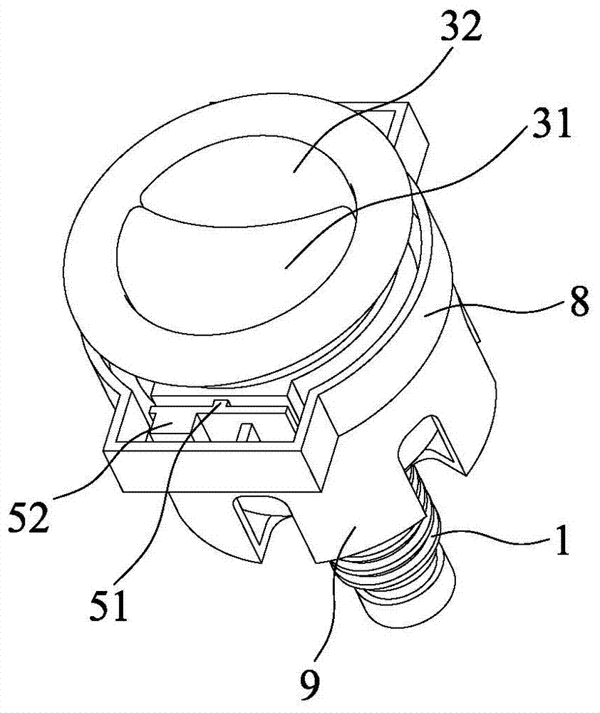
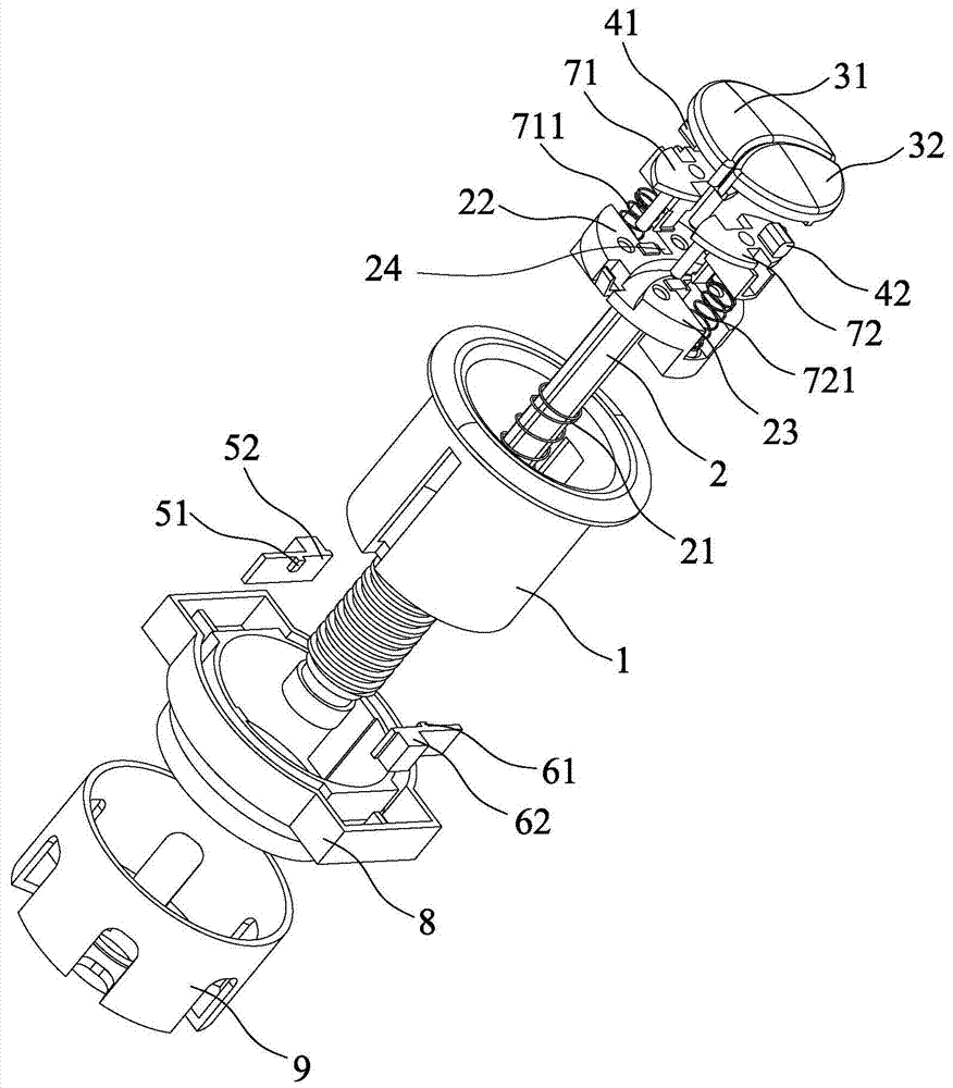
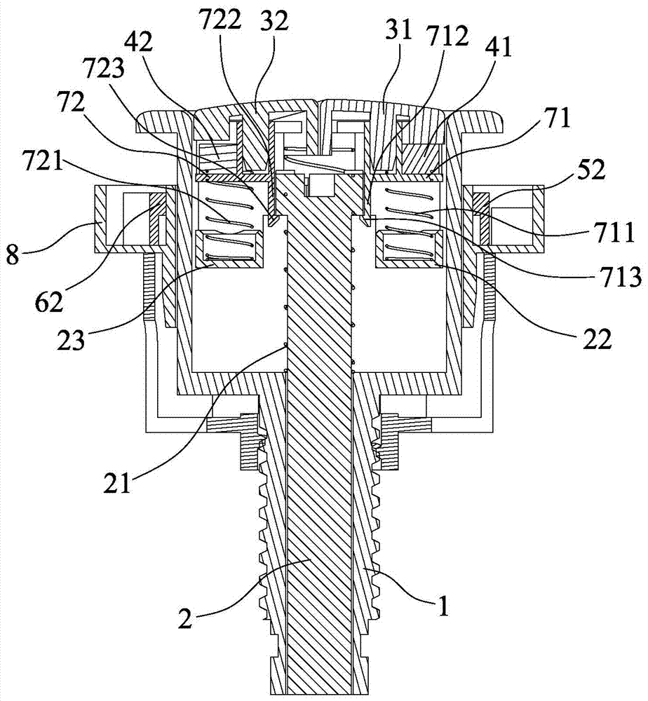
[0045] The present invention will be described in detail below in conjunction with the accompanying drawings and specific embodiments.

[0046] see Figure 1 to Figure 10 As mentioned above, a drainage trigger structure of a drainage valve disclosed in the present invention includes a body 1, a push rod 2, a first button 31, a second button 32, a first magnetic member 41, a second magnetic member 42, and a first sensor 51. The first circuit board 52, the second sensor 61, the second circuit board 62 and the controller (not shown in the figure).

[0047] The push rod 2 is movably installed in the body 1, and a return elastic member 21 is installed between the push rod 2 and the body 1. The return elastic member 21 is usually a return spring, one end of which leans against the body 1, and the other end leans against the push rod 2 superior.

[0048] The first button 31 and the second button 32 are movably installed in the body 1, the first button 31 and the second button 32 ar...


PUM


Abstract

The invention discloses a drain triggering structure of a drain valve. The drain triggering structure comprises a body, a pushing rod, a first button, a second button, a signal triggering mechanism and a controller, wherein the pushing rod is movably arranged in the body; a reset elastic component is arranged between the pushing rod and the body; the first button and the second button are movably arranged in the body; when the first button or the second button is slightly pressed, the signal triggering mechanism is triggered to emit a first control signal or a second control signal; the first control signal or the second control signal is transmitted to the controller, and the controller drives a power-driven mechanism to realize draining; and when the first button or the second button is pressed hard downwards continuously, the pushing rod drives the drain valve to drain. By adopting the drain triggering structure, electric control is realized when the drain triggering structure is electrified; a stroke is short; response is in time; mechanical control is realized when the drain triggering structure is not electrified; and use is convenient.

Description

technical field [0001] The invention relates to the technical field of drain valves, in particular to a drain trigger structure of the drain valve. Background technique [0002] In the prior art, there are usually three control modes of the drain valve: mechanical control; electronic control; both mechanical and electronic control, but separate controls. [0003] Among them, the mechanical control refers to pressing the first button or the second button to make the control end drive the inner core pipe to lift up and down in different strokes in the drain valve body, so as to realize half-row drainage or full-row drainage. The mechanical control has problems such as laborious operation, too long pressing stroke, and bad operating feel. [0004] Electronic control means that the sensor is installed on the first button and the second button, and the signal receiving part is installed on the drain valve body. The signal receiving part is connected with the controller. When the...

Claims


Application Information

Patent Timeline
Patent Type & Authority Applications(China)
IPC IPC(8): F16K31/02F16K31/06F16K31/60
CPCF16K31/02F16K31/0675F16K31/60
Inventor 金忠成彭海松吴琳李仁忠
Owner XIAMEN JIAPULE ELECTRONICS TECH
Learn More