An electrical emergency repair device

A technology of electric power emergency repair and accommodating cavity, which is applied in the field of electric power, which can solve the problems of unstable power supply connection, shortened service life, poor lighting effect, etc., and achieve the effect of saving and unwinding lines, simple structure and preventing damage

Inactive Publication Date: 2018-05-04
YANCHENG HARLEY POWER DRIVE & INTELLIGENT EQUIP IND RES INST CO LTD
View PDF7 Cites 1 Cited by
  • Summary
  • Abstract
  • Description
  • Claims
  • Application Information

AI Technical Summary

Problems solved by technology

However, in the process of electric emergency repair at night, the light source is an important prerequisite for determining the efficiency and safety of emergency repair. In the traditional emergency repair process, mobile light sources are generally used, but their irradiation time is limited and the lighting effect is poor, which is difficult to meet the long-term emergency repair work. , there are also many existing ones that use batteries for power supply, but their power supply connection lines are long, and they are easily affected by external factors such as dragging and pulling, resulting in unstable power supply connections. Too long power supply lines are not conducive to retractable and long-term exposure The service life is shortened in the outside world. At the same time, manual plugging is used during the power supply process. Due to the weak night vision, the plugging safety is low, and it is easy to induce electric shock accidents, which poses a large safety hazard.

Method used


Image

  • An electrical emergency repair device
  • An electrical emergency repair device
  • An electrical emergency repair device

Examples


Embodiment Construction

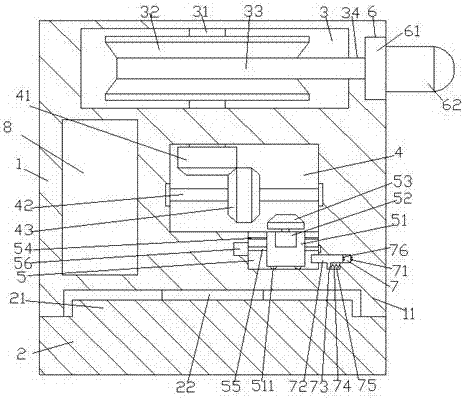
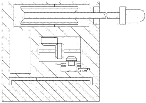
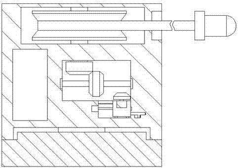
[0021] Such as Figure 1-Figure 6 As shown, an electric emergency repair device of the present invention includes a base 2 and a box body 1 installed above the base 2. The box body 1 is provided with a first accommodating cavity 3, and the first accommodating cavity 3 has a right The outer wall of the box 1 on the side is provided with a counterbore 6, and a perforation 34 is provided between the counterbore 6 and the first accommodation chamber 3, and the box body 1 at the bottom of the first accommodation chamber 3 A second accommodating chamber 4 is provided inside, a first sliding groove 5 is provided at the inner bottom of the right side of the second accommodating chamber 4, and a second sliding groove 7 is provided in the inner wall of the right side of the first sliding groove 5. The bottom of the second sliding groove 7 is provided with a guide groove 75, and the first housing chamber 3 is provided with a first rotating shaft 31 extending downward and extending into t...


PUM


Abstract

The invention discloses a power repair device. The power repair device comprises a base, and a box body mounted above the base; a first accommodating cavity is formed in the box body; a counter bore is formed in the outer side wall of the box body and located on the right side of the first accommodating cavity; a through hole is formed between the counter bore and the first accommodating cavity; a second accommodating cavity is formed in the box body and located at the bottom of the first accommodating cavity; a first slide groove is formed in the bottom in the right side of the second accommodating cavity; a second slide groove is formed in the inner wall of the right side of the first slide groove; a guide groove is formed in the bottom of the second slide groove; a first rotating shaft for downwards elongating and extending into the second accommodating cavity is arranged in the first accommodating cavity; a collecting-releasing disc is fixedly arranged on the outer surface of the first rotating shaft in the first accommodating cavity, and is provided with a power supply wire; the right side end surface of the power supply wire penetrates through the through hole and extends into the counter bore; a clamping block fixedly connected with the tail end of the right side of the power supply wire is arranged in the counter bore; and an illuminating lamp part is arranged on the right side of the clamping block. The power repair device is simple in structure and convenient to operate, saves more labors in circuit collection and release, can realize automatic power supply and power failure, is high in safety, is higher in circuit protecting capacity, prolongs the service life, and can satisfy the power repair illuminating demands.

Description

technical field [0001] The invention relates to the technical field of electric power, in particular to an electric power emergency repair device. Background technique [0002] my country is a big power consumer country, and the increase in power consumption at night often causes electrical components or wires to overload and cause power failures, resulting in power repairs that often occur at night. However, in the process of electric emergency repair at night, the light source is an important prerequisite for determining the efficiency and safety of emergency repair. In the traditional emergency repair process, mobile light sources are generally used, but their irradiation time is limited and the lighting effect is poor, which is difficult to meet the long-term emergency repair work. , there are also many existing ones that use batteries for power supply, but their power supply connection lines are long, and they are easily affected by external factors such as dragging and...

Claims


Application Information

Patent Timeline
Patent Type & Authority Patents(China)
IPC IPC(8): F21S9/02F21V23/00F21V21/14
CPCF21S9/022F21V21/14F21V23/002
Inventor 于广滨
Owner YANCHENG HARLEY POWER DRIVE & INTELLIGENT EQUIP IND RES INST CO LTD
Why Eureka
Try Eureka