Judgment method for tool-workpiece contact area

A judging method and workpiece technology, applied in the direction of metal processing machinery parts, manufacturing tools, metal processing equipment, etc., can solve problems such as difficult to guarantee accuracy, inability to balance efficiency and precision, time-consuming and labor-intensive, etc.

Inactive Publication Date: 2017-06-30
WUHAN UNIV OF SCI & TECH +1
View PDF5 Cites 3 Cited by
  • Summary
  • Abstract
  • Description
  • Claims
  • Application Information

AI Technical Summary

Problems solved by technology

In practical applications, the Boolean operation method has certain advantages in processing some low-axis simple surface processing problems, but in the five-axis complex surface processing, it is time-consuming and labor-intensive, and the accuracy is difficult to guarantee; although the Z-map operation method can satisfy Accuracy requirements for five-axis complex surface machining, but this method cannot balance efficiency and accuracy

Method used


Image

  • Judgment method for tool-workpiece contact area
  • Judgment method for tool-workpiece contact area
  • Judgment method for tool-workpiece contact area

Examples


Embodiment Construction

[0050] In order to make the object, technical solution and advantages of the present invention clearer, the present invention will be further described in detail below in conjunction with the accompanying drawings and embodiments. It should be understood that the specific embodiments described here are only used to explain the present invention, not to limit the present invention. In addition, the technical features involved in the various embodiments of the present invention described below can be combined with each other as long as they do not constitute a conflict with each other. The present invention will be further described in detail below in combination with specific embodiments.

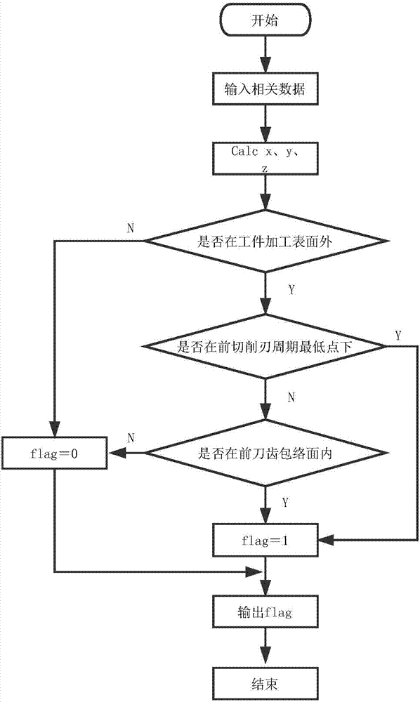
[0051] like figure 1 Shown is a schematic flowchart of a method for judging a contact area according to an embodiment of the present invention. In this embodiment, it is preferable to use five-axis machining as an example to determine the contact area, but this is not limited in the presen...


PUM


Abstract

The invention discloses a judgment method for a tool-workpiece contact area. The judgment method mainly comprises the following steps of: separately establishing a tool coordinate system and a workpiece coordinate system, and determining description, in the two coordinate systems, at the same moment of a cutting edge differential element; determining whether the cutting edge differential element is outside a workpiece processing surface or not; determining whether the cutting edge differential element is under the lowest point of a last cutting edge period or not; determining whether the cutting edge differential element is within a front cutter tooth enveloping surface or not; and according to the step, determining whether the cutting edge differential element is within an effective contact area or not. The algorithm adopted by the technical scheme overcomes the defects such as low efficiency and a complex process in the prior art, has the characteristics of short calculating time and high predicating precision, can integrate efficiency and precision better in aspect of five-axis complex curved surface processing, and greatly optimizes a calculating process of tool cutting force.

Description

technical field [0001] The invention belongs to the field of cutting processing, and in particular relates to a method for judging a tool-workpiece cutting contact area based on the classification of cutting edge elements. Background technique [0002] In the cutting process, in order to ensure the machining accuracy of the workpiece, it is necessary to closely monitor the state of the tool and the workpiece during the cutting process. Cutting force is the force required for the tool to cut into the workpiece and remove chips. It is one of the important physical phenomena in the cutting process. Since the cutting force is the direct factor that causes the deformation of the tool and the workpiece, it is also the key to monitor the state of the tool and the workpiece during the cutting process. Important basis, accurate prediction of cutting force is of great significance for better research on cutting mechanism and planning tool trajectory. [0003] In order to judge whethe...

Claims


Application Information

Patent Timeline
Patent Type & Authority Applications(China)
IPC IPC(8): B23Q17/22
CPCB23Q17/2241
Inventor 段现银彭芳瑜朱泽润蒋国璋周敏
Owner WUHAN UNIV OF SCI & TECH
Why Eureka
Try Eureka