Curve telescopic mechanical arm

A telescopic, manipulator technology, applied in the field of manipulators, can solve the problem that the arm cannot be universally driven

Active Publication Date: 2017-06-30
ZHEJIANG HOUDAR INTELIGENT TECH CO LTD
View PDF5 Cites 1 Cited by
  • Summary
  • Abstract
  • Description
  • Claims
  • Application Information

AI Technical Summary

Problems solved by technology

[0003] The invention provides a curved telescopic manipulator that can drive each segment of the arm to expand and contract with only one drive structure, which solves the problem that the existing multi-segment structure of the manipulator cannot use a common drive structure between each segment of the arm

Method used


Image

  • Curve telescopic mechanical arm
  • Curve telescopic mechanical arm
  • Curve telescopic mechanical arm

Examples


Embodiment 1

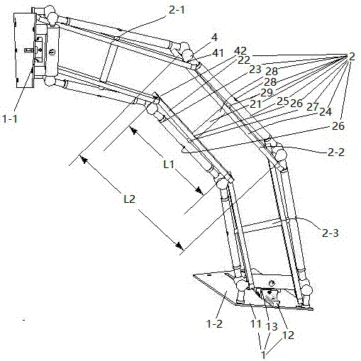
[0023] Embodiment one, see figure 1 , a curved telescopic manipulator, including a connecting base assembly 1 and an arm 2.

[0024] There are two connecting seat assemblies 1. The two connecting seat assemblies 1 are respectively the first connecting seat assembly 1-1 and the last connecting seat assembly 1-2. Both the first connecting seat assembly 1-1 and the last connecting seat assembly 1-2 include a fixed seat 11, a slide rail 12 arranged on the fixed seat and a movable seat 13 slidably connected to the slide rail. The first connecting seat assembly 1-1 also includes a driving mechanism for driving the movable seat to slide on the slide rail (the driving mechanism is not shown in the figure), and the driving mechanism is an air cylinder.

[0025]Arm 2 has 3 sections. The three arms 2 are respectively the first arm 2-1, the middle arm 2-2 and the last arm 2-3. The arm 2 includes a first rod 22 in the central axis 21, an outer first rod 23, an inner second rod 24, an o...

Embodiment 2

[0031] Embodiment two, the difference with embodiment one is:

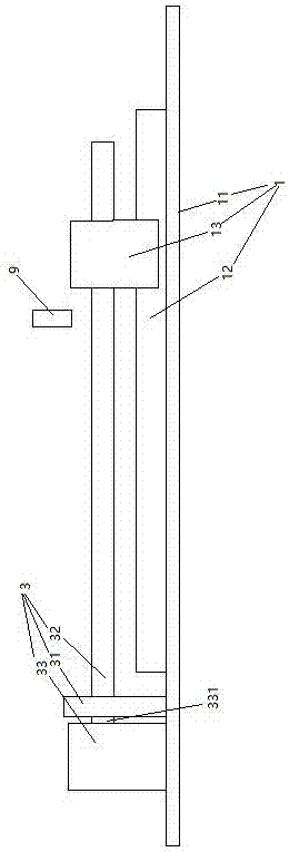
[0032] see figure 2 , the driving mechanism 3 provided on the first connecting seat assembly 1 includes a screw rod 32 and a driving motor 33 . One end of the screw rod 32 is threaded on the movable seat 13, and the other end is fixed together with the power output shaft 331 of the driving motor through a connector. A bearing seat 31 supporting the screw rod 32 is also provided on the fixing seat 11 . The connecting seat assembly 1 is also provided with a filler nozzle 9 for filling oil toward the slide bar 12 . During use, the screw mandrel 32 is driven to rotate by the driving motor 33 , and the screw mandrel 32 drives the movable seat 13 to slide on the slide rail 12 .

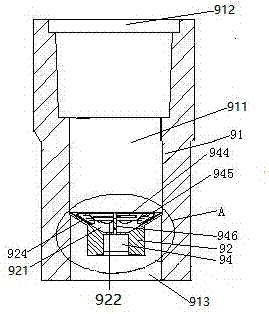
[0033] see image 3 , The filler nozzle 9 includes a filler nozzle body 91 and a filter plate 92 . The fuel nozzle body 91 is a cylindrical structure extending in the vertical direction. A flow channel 911 is provided in the fuel nozzle ...

Embodiment 3

[0037] Embodiment three, the difference with embodiment two is:

[0038] see Figure 6 , The driving mechanism is also provided with a control unit 37 and an overload detection switch 38 . The screw rod 32 is provided with a driven helical gear 322 and retaining springs blocking both ends of the driven helical gear 322 to prevent the driven helical gear 322 from moving axially. . A driving helical gear 332 is slidably sleeved on the power output shaft 331 of the driving motor in the axial direction. The driven helical gear 322 meshes with the driving helical gear 332 . A prism section 333 is provided on the power output shaft 331 of the driving motor. The driving helical gear 332 is provided with polygonal holes matching the prism segments. The driving helical gear 332 is axially movably sleeved on the power output shaft 331 of the drive motor and cooperates with the prism section 333 through the polygonal hole to transmit force when sliding and rotating. Both ends of th...


PUM


Abstract

The invention relates to mechanical arms. A curve telescopic mechanical arm comprises a plurality of joints of arm bodies which are sequentially connected together. Each arm body comprises a middle shaft, wherein one end of the middle shaft is rotationally connected with a first inner rod and a first outer rod, and the other end of the middle shaft is rotationally connected with a second inner rod and a second outer rod. According to the adjacent two joints of arm bodies, the first inner rod of one joint of arm body is hinged to the spherical surface of the first outer rod of the other joint of arm body together, the second inner rod of one joint of arm body is hinged to the spherical surface of the second outer rod of the other joint of arm body, the first outer rod of one joint of arm body is hinged to the spherical surface of the first inner rod of the other joint of arm body together, the second outer rod of one joint of arm body is hinged to the spherical surface of the second inner rod of the other joint of arm body together, and the distance between two hinge points of each first inner rod is smaller than the distance between two hinge points of the corresponding second inner rod. The curve telescopic mechanical arm has the beneficial effect that only one drive structure is needed for driving all joints of arm bodies to stretch and contract; and the problem that a drive structure is not universal for all joints of arm bodies of an existing mechanical arm of a multi-joint structure is solved.

Description

technical field [0001] The invention relates to a manipulator, in particular to a curved telescopic manipulator. Background technique [0002] In automated production, manipulators are used to transfer objects. There are only two ways for the manipulator to transfer objects: one is the structural form of a multi-axis single-section arm, which completes the transfer of objects by driving the rotation and / or translation of the arm. This method requires a larger movement space and prevents Surrounding objects will interfere with the movement of the manipulator; the other is the structural form of a multi-section arm, such as the digging arm of an excavator with a bucket installed. Existing manipulators with multi-section arms have the following deficiencies: the adjacent sections of the arm are independently designed to be driven by a drive mechanism such as an oil cylinder. In order to introduce oil to the oil cylinder, an oil circuit needs to be laid, so there are many drive...

Claims


Application Information

Patent Timeline
Patent Type & Authority Applications(China)
IPC IPC(8): B25J18/02B25J9/14B25J9/12
CPCB25J9/123B25J9/144B25J18/025
Inventor 刘小雄邓勇胡普查芮长江侯新宇李昆张钟伟
Owner ZHEJIANG HOUDAR INTELIGENT TECH CO LTD
Why Eureka
Try Eureka