
A torque control method, device and system for an electric vehicle

A torque control and torque technology, applied in the field of automatic control, can solve the problems of reducing output torque, poor driving experience, and slope distance, etc., and achieve the effect of reducing slope distance and fast response to torque setting

Active Publication Date: 2019-09-20
合肥阳光电动力科技有限公司
View PDF5 Cites 0 Cited by
  • Summary
  • Abstract
  • Description
  • Claims
  • Application Information

AI Technical Summary

Problems solved by technology

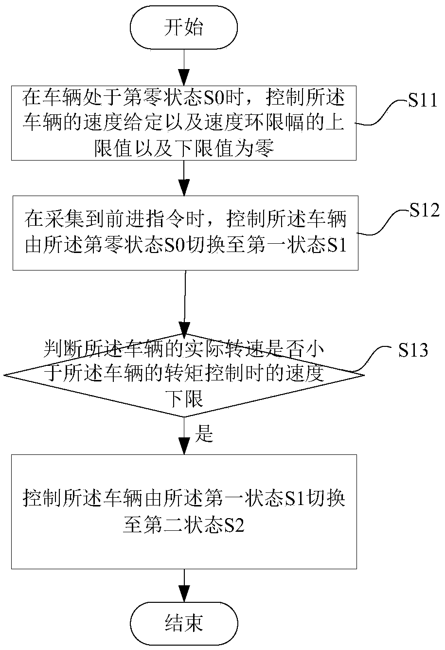
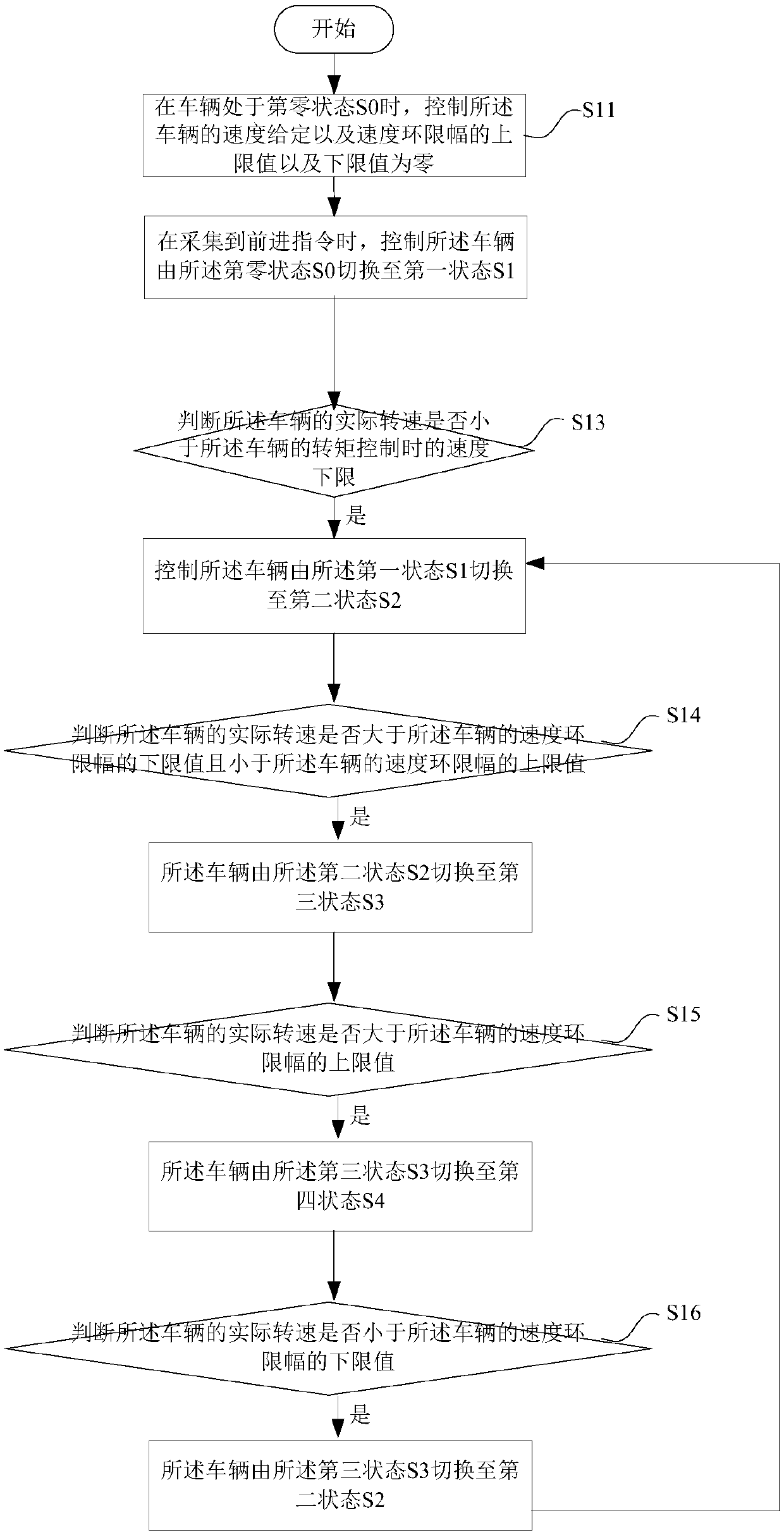
In order to prevent the car from sliding downhill, most new energy vehicles have the function of standing on the slope. It collects the current speed information and gradually increases the torque given at this time, or according to the speed information at this time, the vehicle control system is changed from the torque control mode to Switch to the speed control mode, and use the speed closed-loop method to realize the slope, but due to the delay in the response time, the slope is not timely enough, often resulting in a certain slope distance, and the driving experience is poor
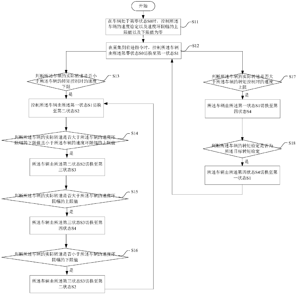
[0003] Moreover, the inventor also found that when the current speed of the new energy vehicle exceeds the set speed, it is necessary to reduce the output torque at this time to limit the actual speed to not exceed the speed limit value
Specifically, at present, when it is detected that the actual vehicle speed exceeds the speed limit, the given torque is gradually reduced until the actual speed is lower than the speed limit value, or after the speed is found to exceed the speed control mode, the speed loop is added to utilize the speed The output compensation torque of the ring is given, so that the actual speed returns to the torque limit range, but the current processing method will cause large speed overshoot and slow response speed

Method used


Image

  • A torque control method, device and system for an electric vehicle
  • A torque control method, device and system for an electric vehicle
  • A torque control method, device and system for an electric vehicle

Examples


Embodiment Construction

[0048]The following will clearly and completely describe the technical solutions in the embodiments of the present invention with reference to the accompanying drawings in the embodiments of the present invention. Obviously, the described embodiments are only some, not all, embodiments of the present invention. Based on the embodiments of the present invention, all other embodiments obtained by persons of ordinary skill in the art without making creative efforts belong to the protection scope of the present invention.

[0049] In order to solve the problem in the prior art that the vehicle slides downhill and the speed overshoot is large and the response speed is slow when overspeeding, the present invention provides a torque control method, device and system for an electric vehicle. When the vehicle is controlled, the given speed is the lower speed limit of the vehicle under torque control, the upper limit of the speed loop limiter of the vehicle is the preset torque given max...


PUM


Abstract

The invention provides a torque control method, device and system of an electric vehicle. When the condition that a vehicle generates a slope sliding phenomenon is judged, the speed of the vehicle is controlled into the speed lower limit during the vehicle torque control; the speed ring amplitude limiting upper limit value of the vehicle is controlled to be the preset torque given maximum value; the speed ring amplitude limiting lower limit value of the vehicle is controlled to be the target torque given value, i.e., the speed ring is immediately added; the input value of the speed ring is set, so that the torque given response is fast; the slope sliding distance is reduced. In addition, the scheme also has the advantages that when the current vehicle speed exceeds the set rotating speed, the rotating speed of the vehicle is fast limited to the speed upper limit through setting the rotating speed giving of the speed ring; the rotating speed overshooting is reduced; the response is high. The uniform speed / torque control strategy based on a state machine is provided for the electric vehicle slope sliding, normal running (advancing and retreating) and speed limit exceeding.

Description

technical field [0001] The invention relates to the technical field of automatic control, and more specifically, to a torque control method, device and system for an electric vehicle. Background technique [0002] When the car is started on a half-slope, due to its own gravity, it will slide downhill. In order to prevent the car from sliding downhill, most new energy vehicles have the function of standing on the slope. It collects the current speed information and gradually increases the torque given at this time, or according to the speed information at this time, the vehicle control system is changed from the torque control mode to Switch to the speed control mode and use the speed closed-loop method to realize the slope, but due to the delay in the response time, the slope is not timely enough, often resulting in a certain slope distance, and the driving experience is poor. [0003] Moreover, the inventor also found that when the current speed of the new energy vehicle e...

Claims


Application Information

Patent Timeline
Patent Type & Authority Patents(China)
IPC IPC(8): B60L15/20
CPCB60L15/20B60L15/2081B60L2240/12B60L2240/421B60L2240/423Y02T10/72
Inventor 于安博朱博
Owner 合肥阳光电动力科技有限公司
Learn More