
Control system of booster bike

A control system and moped technology, applied in vehicle parts, bicycle accessories, optical signals, etc., can solve the problems of strenuous pedaling, wasted power, and the inability of rear wheel components to effectively relieve the pedaling load of riders.

Active Publication Date: 2017-06-30
漳浦桂宏工业有限公司
View PDF6 Cites 5 Cited by
  • Summary
  • Abstract
  • Description
  • Claims
  • Application Information

AI Technical Summary

Problems solved by technology

[0006] 1. The driving force of the rear wheel assembly cannot effectively relieve the pedaling load of the rider. In the face of difficult road conditions, it is still necessary to step on it hard (making the pedal running faster than the acceleration of the moped) to overcome it, resulting in physical hardship and fatigue for the rider , which is a shortcoming in the use of the conventional patent structure
[0007] 2. When the inertial acceleration force of the car body is increased due to changes in road conditions (downhill), if it cannot respond in time to reduce the motor power assist (that is, the driving force described in the above known patent), the car body will form unnecessary acceleration and Braking causes the wasted consumption of electric power again, is the shortcoming in the use of conventional patent structure two
[0008] Therefore, how to address the above-mentioned conventional patent structure cannot timely respond to changes in the inertial force of the car body in different road conditions, nor can it flexibly output power assistance that can meet the needs of the rider according to the resistance formed by different road conditions on the car body, resulting in a The body forms unnecessary acceleration and braking, which also causes waste of power, and causes the rider to step hard and fatigue. The creators have made improvements and creators, which are the difficulties to be solved for this case.

Method used


Image

  • Control system of booster bike
  • Control system of booster bike
  • Control system of booster bike

Examples


Embodiment Construction

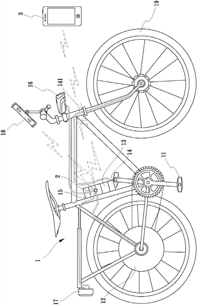
[0028] Examples, see Figure 1 to Figure 6 As shown, a control system of a power-assisted vehicle of the present invention includes: a power-assisted vehicle 1, including a pedal 11 driven by pedaling, a power-assisted motor 12 for driving the power-assisted vehicle, and a battery 13 required for the operation of the power-assisted motor:

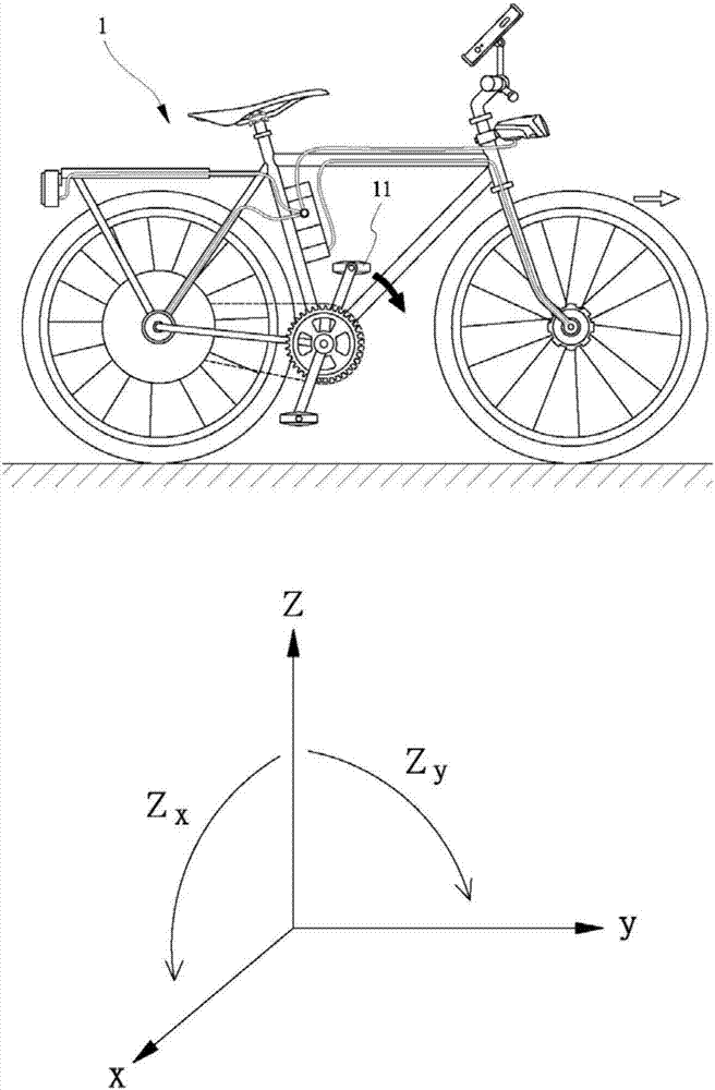
[0029] An acceleration sensor 15 is arranged on the body of the power-assisted vehicle 1 and detects the driving acceleration value of the power-assisted vehicle 1 and simultaneously detects the running acceleration value of the pedal 11 driven by stepping on it.

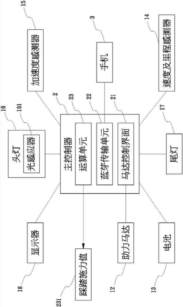
[0030] A main controller 2 is installed on the power-assisted vehicle 1, and the main controller 2 receives the driving acceleration value of the power-assisted vehicle 1 detected by the acceleration sensor 15, and the running acceleration value of the pedal 11 detected by induction, and outputs an adjustment signal to the power-assisted motor 12 , battery 13, in order to control...


PUM


Abstract

The invention discloses a control system of a booster bike. The control system of the booster bike comprises an acceleration sensor and a main controller, wherein the acceleration sensor is arranged on a booster bike body and used for detecting the running acceleration value of the booster bike and detecting the treading running acceleration value of pedals simultaneously; and the main controller is arranged on the booster bike and used for receiving the running acceleration value, detected by the acceleration sensor, of the booster bike, distinguishing, sensing and detecting the treading running acceleration value of the pedals, and outputting an adjusting signal to a booster motor and a battery so as to control output of the booster motor and the battery. When the running acceleration value of the pedals is larger than the running acceleration value of the booster bike, the main controller judges that the booster bike accepts increase of running resistance of the road condition or the wind power, and improves the output of the booster motor and the battery, the control system can effectively assist a rider in easily overcoming running resistance caused by tough road conditions without treading on the pedals hard, and labor and fatigue of the rider are relieved.

Description

technical field [0001] The invention relates to the technical field of controlling auxiliary power output of a booster vehicle, in particular to a control system of a booster vehicle. Background technique [0002] At present, riding a bicycle or a locomotive has become an indispensable means of transportation for ordinary people, especially bicycles. In addition to transportation, it also has more sports and fitness functions. However, the purely mechanical device of the bicycle must be overcome by the rider All the resistance in real road conditions (such as climbing gravity and air resistance) will be relatively hard for people with poor physical fitness. [0003] Recently, industry players have introduced bicycle structures with auxiliary power, such as the "Bicycle Transmission System" patent case of China Taiwan Announcement No. M520049. This patent is as described in claim 1: "1. A bicycle transmission system, which includes : a support body, which is detachably suspe...

Claims


Application Information

Patent Timeline
IPC IPC(8): B62M6/50B62J6/00
CPCB62J6/01B62M6/50
Inventor 李文嵩
Owner 漳浦桂宏工业有限公司
Learn More