Yarn guiding plate, yarn receiving device, and work position operation method

A technology of yarn guide plate and station, which is applied in the direction of transportation and packaging, delivery of filamentous materials, and thin material processing, etc., and can solve the problems of damage and instability of the components of the yarn splicing device

Active Publication Date: 2017-06-30
SAURER SPINNING SOLUTIONS GMBH & CO KG
View PDF9 Cites 6 Cited by
  • Summary
  • Abstract
  • Description
  • Claims
  • Application Information

AI Technical Summary

Problems solved by technology

[0009] In addition, possible jerky or deviating yarn movements from the yarn movement path can lead to friction-related damage to the parts of the splicing device or components in the region of the splicing device

Method used


Image

  • Yarn guiding plate, yarn receiving device, and work position operation method
  • Yarn guiding plate, yarn receiving device, and work position operation method
  • Yarn guiding plate, yarn receiving device, and work position operation method

Examples


Embodiment Construction

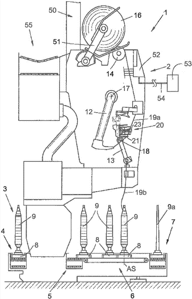
[0038] figure 1 A schematic side view of a station 2 of a winder 1 in the form of an automatic cross-winder winder is shown according to one embodiment.

[0039] As is known, such an automatic cross-winding winder 1 has a plurality of identical stations 2 , here winding positions 2 , between its (not shown) end frames. In the winding position 2, the bobbin 9 used as an unwinding bobbin is rewound into a large package crosswinding bobbin 16 as a winding bobbin.

[0040] The winding position 2 has a yarn splicing device 10 slightly retracted from the normal yarn path for joining the so-called top yarn 19 a from the cross-wound bobbin 16 with the so-called bottom yarn 19 b from the bobbin 9 . Such a yarn connection may be required, for example, when a new bobbin 9 is provided, when the yarn is split, or in a controlled so-called clearing step for removing yarn defects.

[0041] The basic mode of operation of such an automatic cross-winding winder 1 is previously disclosed, for ...


PUM


Abstract

The invention relates to a yarn guiding plate, a yarn receiving device, and a work position operation method. A yarn guiding plate 30 is provided with a yarn guiding finger 34, which comprises a veil 19a used for guiding a to-be-received yarn 19 in a state of connection with a yarn receiving device 20 and a yarn guiding edge 35 of a bottom yarn 19b. The yarn guiding edge 35 is used to form the yarn guiding finger 34, and comprises a first edge part 36 used for guiding the bottom yarn 19b and a second edge part 37 used for guiding the veil 19a. The first edge part 36 is extended from a V-shaped fingertip 39 to a finger root 40, and the first edge part 36 on the finger root 40 is used to form a preset angle alpha in a wrapped manner, and is transited to the other edge part 38. The second edge part 37 is extended from the outer side of the yarn guiding finger 34 opposite to the first edge part 36, and is transited from the fingertip area 39 to the first edge part 36. The yarn guiding plate 30 is characterized in that the first edge part 36 is provided with a recess 41, which is disposed between the finger root 40 and the fingertip 39, and is used for the non-contact moving of the yarn 19 along the yarn motion rout during the operation period of the work position 2.

Description

technical field [0001] The invention relates to a yarn guide plate for a yarn splicing device of a winder station, a yarn splicing device comprising such a yarn guide plate and a method for operating such a station. Background technique [0002] Such yarn splicing devices, in particular for connecting two yarn ends by air, have been known for a long time in relation to the stations of winding machines, such as automatic cross-winding winders, and are explicitly described in a large number of patent documents. [0003] With such yarn splicing devices disclosed in documents DE19510171A1, DE10359570A1, DE10224080A1 and DE102006006390A1, two yarn ends are connected with air flow after yarn breakage or after being cut by a controlled yarn clearer, so that almost the same yarn as the yarn occurs. connector. [0004] Here, the yarn falling onto the surface of the winding package, the so-called yarn end, is picked up by means of a suction nozzle and inserted into the yarn-joining c...

Claims


Application Information

Patent Timeline
Patent Type & Authority Applications(China)
IPC IPC(8): B65H69/06
CPCB65H69/06B65H2701/31B65H57/02
Inventor O·内比格S·斯查顿
Owner SAURER SPINNING SOLUTIONS GMBH & CO KG
Why Eureka
Try Eureka