
Upper air intake furnace end and combustor with same

A technology for a blast stove and a burner base, which is applied in the field of kitchen utensils, can solve the problems of reducing work efficiency, increasing costs, reducing combustion efficiency, etc., and achieves the effects of reducing friction, reducing costs, and improving combustion efficiency.

Pending Publication Date: 2021-05-11
SHENGZHOU YUANJIAN MACHINERY TECH
View PDF0 Cites 0 Cited by
  • Summary
  • Abstract
  • Description
  • Claims
  • Application Information

AI Technical Summary

Problems solved by technology

[0002] Most of the upward-inlet burners in the prior art have complex structures, which affect the appearance and are not easy to clean. In addition, most of the ejector tubes are cast, and the inner edge is rough, and the friction force encountered when the gas flows through is relatively large, which reduces the combustion efficiency
[0003] Moreover, during the installation process, the furnace head with a cup shell structure is usually fixedly connected to the bottom of the cup body first, and then the nozzle is installed on the side wall of the cup body. Sometimes the gas outlet of the nozzle cannot be aligned and installed at one time. The center hole of the damper at the inlet end of the ejector tube needs to be reworked, which increases the cost and reduces the work efficiency

Method used


Image

  • Upper air intake furnace end and combustor with same
  • Upper air intake furnace end and combustor with same
  • Upper air intake furnace end and combustor with same

Examples


Embodiment 1

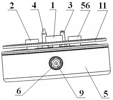
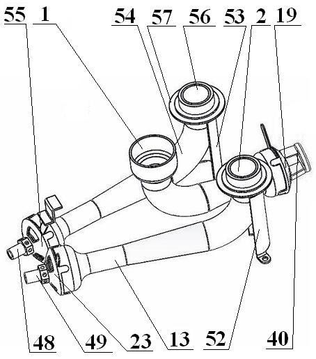
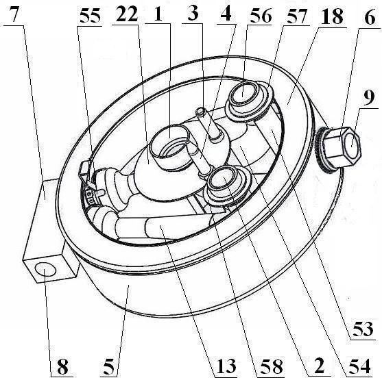
[0033]Embodiment 1: A kind of upward air inlet burner, including burner base 5, central injection tube 25, outer injection tube A13, outer injection tube B54, ventilation seat A6, ventilation seat B7, said burner base 5 is Round cup shape, including annular side walls and circular bottoms connected with the same body, A hole 44, B hole 46, C hole 47 are provided on the side wall of the burner seat 5, and the B hole 46 and C hole 47 is respectively provided with the inner thread that is adapted to the outer thread of the air inlet end of the outer nozzle B48 and the outer nozzle C49. Flared, and respectively fixedly connected to the center damper 19, the outer damper B23, the outer damper C55, the mounting bracket C40 includes an annular body 41 and several connecting pins 42 connected with it, the annular body 41 is provided with an internal Threaded connecting holes 43, several connecting pins 42 are welded with the central damper 19, the central injection pipe 25 is welded w...

Embodiment 2

[0038] Embodiment 2: A kind of burner, on the basis of embodiment 1, will be provided with the outer fire cover seat 10 of outer A pipe 14 and outer B pipe 59 on described secondary air dividing plate 11, and make The outer A tube 14 is inserted into the outlet port 2 of the outer injection A tube, the outer B tube 59 is inserted into the outer injection B tube outlet 56, and the outer fire cover is placed on the outer fire cover seat 10 , and then place the inner fire cover on the gas outlet end 1 of the central injection tube.

[0039] The outer fire cover includes an annular outer lower fire ring 29 formed by casting or stamping stainless steel and an annular outer upper fire ring 28 formed by casting or stamping stainless steel and placed on the outer lower fire ring 29. The outer fire lower ring 29 includes an inner ring A body 32, an upper ring A body 33 and an outer ring A body 34 connected in sequence, and the upper ring A body 33 is provided with several upwardly prot...


PUM


Abstract

The invention provides an upper air intake furnace end simple in structure, attractive, easy to clean, high in combustion efficiency and easy to install and a combustor with the same. The upper air intake furnace end comprises a furnace end base, a center injection pipe, an outer injection pipe A, an outer injection pipe B, a ventilation base A and a ventilation base B. The furnace end base is in a round cup shape and comprises an annular side wall and a round bottom integrally connected with the annular side wall. A hole A, a hole B and a hole C are formed in the side wall of the furnace end base, the hole B and the hole C are provided with internal threads matched with external threads of the air inlet end of an outer nozzle B and the air inlet end of an outer nozzle C respectively, and the air inlet ends of the center injection pipe, the outer injection pipe A and the outer injection pipe B are all made into flared openings and fixedly connected with a center air door, an outer air door B and an outer air door C respectively. A mounting bracket C comprises an annular body and a plurality of connecting feet which are integrally connected with the annular body, the annular body is provided with a connecting hole with an internal thread, and the connecting feet are welded to the central air door.

Description

technical field [0001] The invention relates to kitchen utensils, in particular to an upward air inlet burner and a burner with the burner. Background technique [0002] Most of the upward-inlet burners in the prior art have complex structures, which affect the appearance and are not easy to clean, and most of the ejector tubes are cast, and the inner edge is rough, and the friction force encountered when the gas flows through is relatively large, which reduces the combustion efficiency. [0003] Moreover, during the installation process, the furnace head with a cup shell shell structure is usually fixedly connected to the bottom of the cup body first, and then the nozzle is installed on the side wall of the cup body. Sometimes the gas outlet of the nozzle cannot be aligned and installed at one time. The central hole of the damper at the inlet end of the ejector tube needs to be reworked, which increases the cost and reduces the work efficiency. Contents of the invention ...

Claims


Application Information

Patent Timeline
IPC IPC(8): F23D14/04F23D14/46F23D14/58F24C3/08
CPCF23D14/04F23D14/46F23D14/58F24C3/085
Inventor 胡波楹胡国贤王月忠
Owner SHENGZHOU YUANJIAN MACHINERY TECH
Learn More