Upper and lower double-layer steel bridge beam falling structure for highway bridge and railway bridge and beam falling method of upper and lower double-layer steel bridge beam falling structure

A technology for railway bridges and highway bridges, which is applied in bridges, bridge parts, bridge construction, etc., and can solve problems such as difficult transportation of steel structure modules, large traffic volume, and limited construction sites

Active Publication Date: 2022-04-12
JIANGSU HUNING STEEL MECHANISM
View PDF11 Cites 0 Cited by
  • Summary
  • Abstract
  • Description
  • Claims
  • Application Information

AI Technical Summary

Problems solved by technology

[0009] Purpose of the invention: In order to overcome the above deficiencies, the purpose of the present invention is to provide a double-layer steel bridge drop beam structure for road bridges and railway bridges, which solves the problem that the 62m steel box girder crosses Zhijiang East Road, which is the main traffic in Hangzhou. The main line, the traffic flow is very large, the construction site is limited and the transportation of steel structure modules is difficult

Method used


Image

  • Upper and lower double-layer steel bridge beam falling structure for highway bridge and railway bridge and beam falling method of upper and lower double-layer steel bridge beam falling structure
  • Upper and lower double-layer steel bridge beam falling structure for highway bridge and railway bridge and beam falling method of upper and lower double-layer steel bridge beam falling structure
  • Upper and lower double-layer steel bridge beam falling structure for highway bridge and railway bridge and beam falling method of upper and lower double-layer steel bridge beam falling structure

Examples


Embodiment

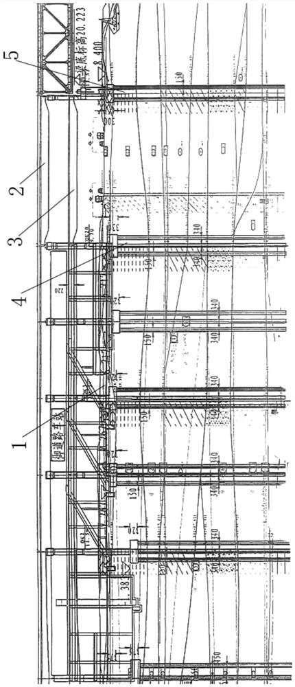
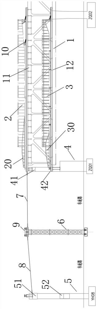
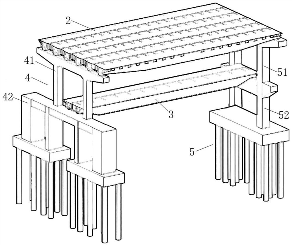
[0056] Such as figure 1 The falling girder structure of the upper and lower double-layer steel bridges of the highway bridge and the railway bridge includes the main bridge 1, the highway composite beam 2, the track composite beam 3, the ZQ1 bridge pier 4, the YH08 bridge pier 5, the support 6, several steel strands-7, Several steel strands 2 8, walking pusher 9, rail clamp 10, highway combined beam guide beam 20 and track combined beam guide beam 30, the ZQ1 pier 4 is connected to the main bridge 1, and the ZQ1 pier 4 and The YH08 pier 5 is on the same straight line, and the ZQ1 pier 4 and the YH08 pier 5 are respectively located on both sides of Shishi Road. The lower steel truss bridge 12, the ZQ1 pier 4 is divided into ZQ1 upper pier 41 and ZQ1 lower pier 42, the YH08 pier 5 is divided into YH08 upper pier 51 and YH08 lower pier 52, and the support 6 is divided into highway composite beam support Frame 61 and track combination beam support frame 62, the upper end of descr...


PUM


Abstract

The invention discloses a highway bridge and railway bridge upper and lower double-layer steel bridge beam falling structure and a beam falling method. The highway bridge and railway bridge upper and lower double-layer steel bridge beam falling structure comprises a main bridge, a highway composite beam, a rail composite beam, a ZQ1 pier, a YH08 pier, a support, a plurality of first steel strands, a plurality of second steel strands, a walking type pushing device, a rail clamping device, a highway composite beam guiding beam and a rail composite beam guiding beam. The road combination beam and the rail combination beam are erected between the ZQ1 upper-layer pier and the YH08 upper-layer pier through the road combination beam guiding beam, the walking type pushing device and the rail clamping device. According to the upper and lower double-layer steel bridge falling beam structure, a whole road combination beam and a track combination beam are spliced and are sequentially pushed to a bridge pier, and then the beams fall to the designed elevation. According to the beam falling method of the upper and lower double-layer steel bridge beam falling structure of the highway bridge and the railway bridge, the installation of the steel bridge with huge volume can be smoothly realized in an installation place with smaller site area and large traffic flow, and the precision requirement of the steel bridge is ensured to meet the requirements of field assembly and design.

Description

technical field [0001] The invention belongs to the technical field of steel structure construction, and in particular relates to a falling beam structure of a double-layer steel bridge on a road bridge and a railway bridge. The invention also relates to a beam dropping method for the upper and lower double-layer steel bridge beam dropping structures of highway bridges and railway bridges. Background technique [0002] Bridges generally refer to structures erected on rivers, lakes and seas to allow vehicles and pedestrians to pass smoothly. Many traditional bridges are pure concrete bridges. With the continuous advancement of technology, many current bridges are combined steel structures and concrete. [0003] The reconstruction project of the Hangzhou urban section of the Shanghai-Hangzhou-Ningbo Expressway has a total length of 2007.8m. As a bridge across the Qiantang River, like many landmark buildings around Hangzhou, it is a combination of modern architectural technolo...

Claims


Application Information

Patent Timeline
Patent Type & Authority Applications(China)
IPC IPC(8): E01D19/00E01D19/02E01D21/00
CPCY02A30/60
Inventor 巫明杰吴立辉兰超宗宁雯厉栋郑睿轩
Owner JIANGSU HUNING STEEL MECHANISM
Why Eureka
Try Eureka