Mine taking-hanging-free overhead person carrying device
A technology for flight attendants and hangers, applied in transportation and packaging, cable railways, motor vehicles, etc., can solve problems such as hidden dangers in the safe operation of overhead passenger devices, turning of passenger devices, etc., to avoid manual removal and hanging of seats, increase the The effect of large wrapping angle and stable work
- Summary
- Abstract
- Description
- Claims
- Application Information
AI Technical Summary
Problems solved by technology
Method used
Image
Examples
Embodiment 1
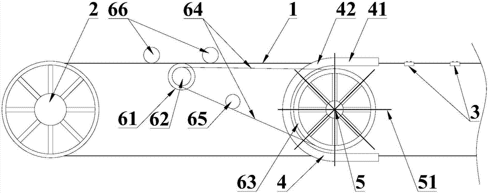
[0029] Such as figure 1 As shown, a mine-used no-picking hanger air passenger device includes a steel wire track 1, a track drive wheel 2, a passenger vehicle 3, a U-shaped slide rail 4, a shift fork 5 and a shift fork drive device; the steel wire track 1 In order to close the loop, the track driving wheels 2 are arranged at both ends of the steel wire track 1 to drive the movement of the steel wire track 1; the passenger car 3 is arranged on the steel wire track 1 and can follow the steel wire The track 1 moves; the two straight sides 41 of the U-shaped slide rail 4 coincide with the two sides of the steel wire track 1; The straight side 41 then moves along the U-shaped slide rail 4 and enters the other side of the steel wire track 1 through the bent portion 42 of the U-shaped slide rail 4 , so that the passenger vehicle 3 turns around.
[0030] The shift fork 5 is fixed below the U-shaped slide rail 4, and the shift fork 5 can rotate around the central axis of the shift for...
Embodiment 2
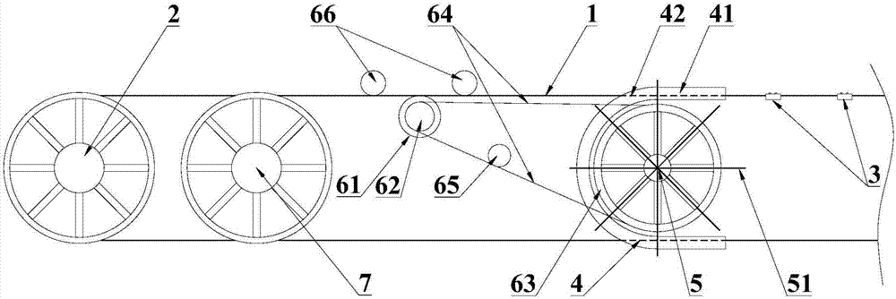
[0037] refer to figure 2 , the difference between this embodiment and the mine-used no-picking rack flight attendant device provided in Embodiment 1 is that: in order to increase the conveying distance of the steel wire track 1, between the pressing wheel 66 and the track driving wheel 1 A secondary drive wheel 7 is also provided, and the steel wire track 1 is wound around the secondary drive wheel 7, thereby increasing the enveloping angle of the steel wire track 1, so that the steel wire track 1 is subject to greater frictional force , the traction force that the steel wire track 1 can transmit becomes larger, so that the traction distance of the steel wire track 1 is also larger.
Embodiment 3
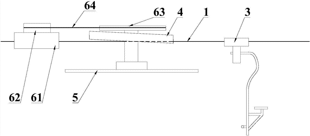
[0039] refer to image 3, the difference between this embodiment and the mine-used no-picking hanger flight attendant device provided in Embodiment 1 is that: along the direction in which the passenger vehicle 3 enters the U-shaped slide rail 4, the U-shaped slide The rail 4 is inclined upwards, so that the passenger car 3 leaves the steel wire track 1 in the U-shaped slide rail 4 first, and then turns into the bending part 42 to reduce the turning resistance of the passenger car 3 , to make the running process smoother.
[0040] Inspired by the above technical solutions, those skilled in the art can also realize the separation of the steel wire track 1 and the passenger vehicle 3 through other solutions; for example Figure 4 In the intersection of the U-shaped slide rail 4 and the steel wire track 1, the steel wire track 1 is inclined downward and passed through the bottom of the U-shaped slide rail 4, so that the passenger car Separated from the wire track 1. or as Fig...
PUM
 Abstract
Description
Claims
Application Information
 - R&D
- Intellectual Property
- Life Sciences
- Materials
- Tech Scout
- Unparalleled Data Quality
- Higher Quality Content
- 60% Fewer Hallucinations
Browse by: Latest US Patents, China's latest patents, Technical Efficacy Thesaurus, Application Domain, Technology Topic, Popular Technical Reports.
© 2025 PatSnap. All rights reserved.Legal|Privacy policy|Modern Slavery Act Transparency Statement|Sitemap|About US| Contact US: help@patsnap.com


