Liquid piston heat engine

A technology of liquid piston and heat engine, applied in the field of thermal energy and power, can solve the problems that are difficult to realize, large Stirling engine, Stirling engine with limited heating efficiency and cooling efficiency

Inactive Publication Date: 2012-05-02
ZEROQ SCI & TECH
View PDF5 Cites 13 Cited by
  • Summary
  • Abstract
  • Description
  • Claims
  • Application Information

AI Technical Summary

Problems solved by technology

Since the sealed shell (such as cylinder liner, etc.) and the solid piston are both solid structural parts, there are inevitably problems such as machining errors, force deformation, cold and heat deformation, and wear. If logically, mathematically and geometrically Scientifically analyzing the characteristics of this mechanism carefully, it can be concluded that the all-round and complete sealing of the solid piston and the sealed shell of the traditional piston heat engine can never be solved.
The traditional heat engine is represented by the Stirling engine. The Stirling engine is limited by the movement law of the crank and connecting rod mechanism. It is difficult to realize the Stirling cycle in the true sense, let alone use a heat engine to selectively Implement Stirling and Carnot cycles
Not only that, the heating and cooling efficiency of the Stirling engine is very limited, so it is difficult to make a large Stirling engine

Method used


Image

  • Liquid piston heat engine
  • Liquid piston heat engine
  • Liquid piston heat engine

Examples


Embodiment 1

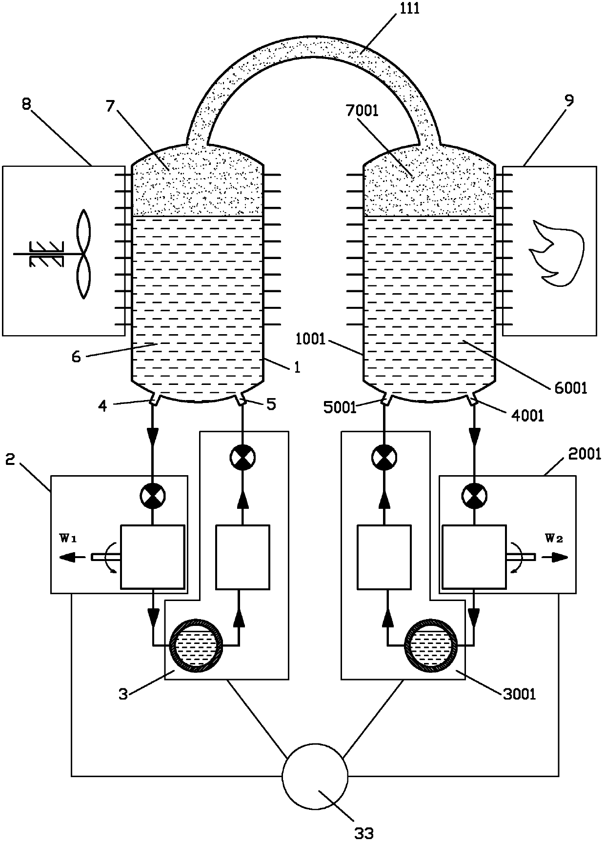
[0050] Such as figure 1 The liquid piston heat engine shown includes a cold gas liquid cylinder 1, a hot gas liquid cylinder 1001, a cold hydraulic power mechanism 2, a hot hydraulic power mechanism 2001, a cold liquid working medium return system 3 and a hot liquid working medium return system 3001. The liquid cylinder 1 communicates with the hot gas liquid cylinder 1001 through the gas working fluid communication pipeline 111, a cooler 8 is provided on the cold gas liquid cylinder 1, and a heater 9 is provided on the hot gas liquid cylinder 1001;

[0051] The cold gas-liquid cylinder 1 is provided with a cold liquid working medium outlet 4 and a cold liquid working medium return port 5, and the cold liquid working medium outlet 4 communicates with the power liquid inlet of the cold hydraulic power mechanism 2, and the cold hydraulic power The liquid outlet of the mechanism 2 communicates with the cold liquid working medium return system 3, and the cold liquid working medium...

Embodiment 2

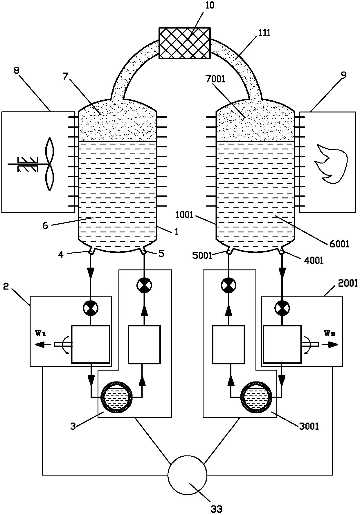
[0055] Such as figure 2 The difference between the shown liquid piston heat engine and Embodiment 1 is that a regenerator 10 is provided on the gas working fluid communication pipeline 111 .

Embodiment 3

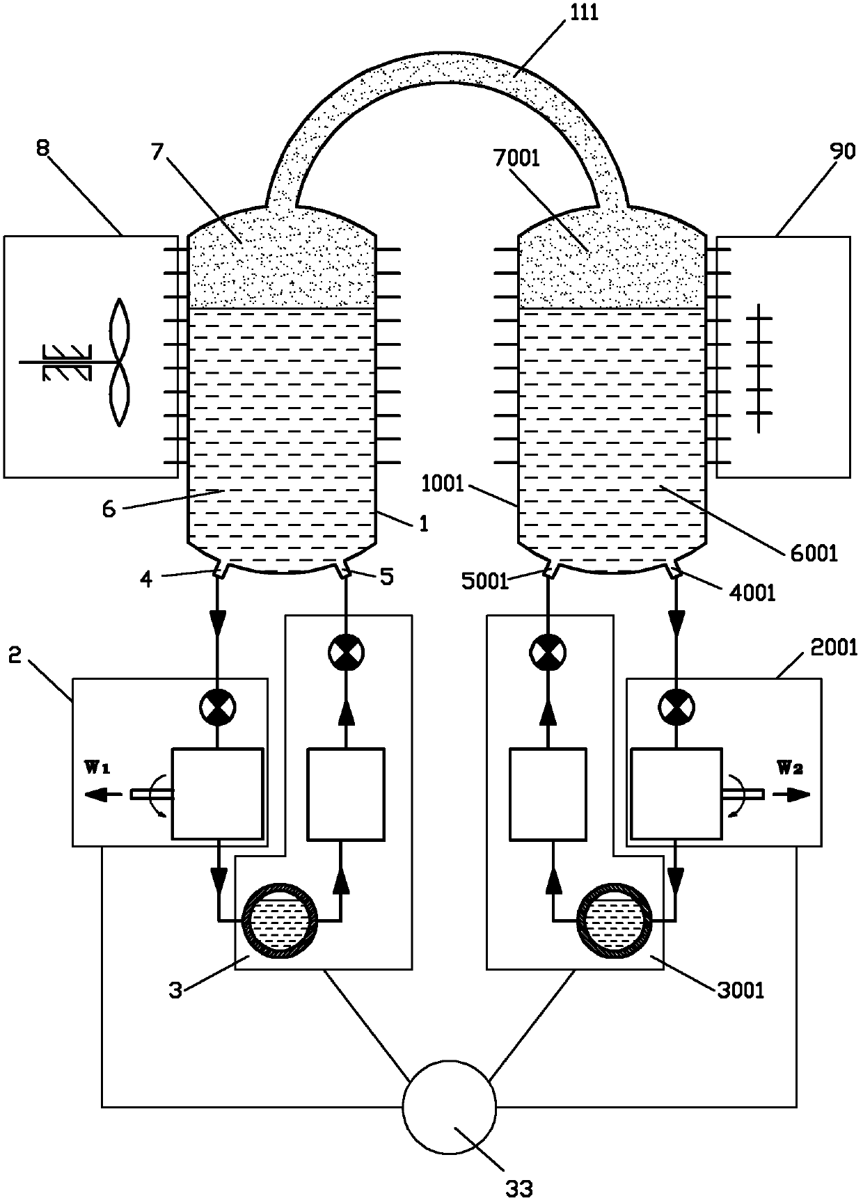
[0057] Such as image 3 The difference between the shown liquid piston heat engine and Embodiment 1 is that the heat source of the heater 9 is set as a low-grade heat source 90 .


PUM


Abstract

The invention discloses a liquid piton heat engine which comprises a cold air hydraulic cylinder, a hot air hydraulic cylinder, a cold hydraulic power mechanism, a hot hydraulic power mechanism, a cold liquid medium return system and a hot liquid medium return system, wherein the cold air hydraulic cylinder is communicated with the hot air hydraulic cylinder through an air medium communicating pipeline, a cooler is arranged on the cold air hydraulic cylinder, a heater is arranged on the hot air hydraulic cylinder, a cold liquid medium outlet of the cold air hydraulic cylinder is communicated with a cold liquid medium return hole through the cold hydraulic power mechanism and the cold liquid medium return system, a hot liquid medium of the hot air hydraulic cylinder is communicated with a hot liquid medium return hole through the hot hydraulic power mechanism and the hot liquid medium return system, and the cold hydraulic power mechanism, the cold liquid medium return system, the hot hydraulic power mechanism and the hot liquid medium return system are controlled by a progress control mechanism. According to the invention, a piston crank connecting rod mechanism of an engine is omitted, and a large-power thermomotor with high efficiency and small volume and light weight can be manufactured.

Description

technical field [0001] The invention relates to the field of thermal energy and power, in particular to a liquid piston heat engine. Background technique [0002] At present, the most important parts in a piston heat engine are the piston and the heat exchanger. The function of the piston is sealing and force transmission, that is, the piston should try to prevent the high-pressure gas working medium from leaking and transmit the pressure of the high-pressure gas working medium. go out. The pistons of traditional piston heat engines are all solid components with certain geometric shapes. For this reason, due to problems such as machining errors, force deformation, cold and heat deformation, and wear, the pistons and matching parts (cylinder liners, etc.) ) sealing problem, especially the sealing problem between the piston of the rotary engine and the fitting (the casing of the rotary engine), has always been one of the key issues affecting the efficiency and life of the eng...

Claims


Application Information

Patent Timeline
Patent Type & Authority Applications(China)
IPC IPC(8): F02G1/043F02G1/055F02G1/057F02G1/045
CPCY02T10/125Y02T10/12
Inventor 靳北彪
Owner ZEROQ SCI & TECH
Why Eureka
Try Eureka