Hybrid-power unmanned aerial vehicle with four auxiliary wings and control method thereof

A technology of hybrid power and unmanned aerial vehicles, which is applied in the direction of rotorcraft, power plant type, unmanned aircraft, etc., can solve the problems of limited endurance, large power consumption, and difficult manipulation, so as to improve endurance and improve The effect of flexibility and long battery life

Inactive Publication Date: 2016-08-24
SHENYANG AEROSPACE UNIVERSITY
View PDF4 Cites 12 Cited by
  • Summary
  • Abstract
  • Description
  • Claims
  • Application Information

AI Technical Summary

Problems solved by technology

Electric drones are easy to maneuver and have high sensitivity, but they have poor wind resistance and poor endurance. Especially when the load is heavy, they need to consume a lot of power to overcome gravity; Difficult to operate and poor in sensitivity, the current small oil-powered UAVs mostly use the method of controlling the air intake of the intake valve to control the speed of the blades, and the response to the control signal is relatively sluggish
[0003] Nowadays, both the traditional helicopter architecture and the rapidly popularized multi-rotor architecture have developed rapidly in the field of UAV manufacturing. Both architectures are rela

Method used


Image

  • Hybrid-power unmanned aerial vehicle with four auxiliary wings and control method thereof
  • Hybrid-power unmanned aerial vehicle with four auxiliary wings and control method thereof
  • Hybrid-power unmanned aerial vehicle with four auxiliary wings and control method thereof

Examples


Embodiment Construction

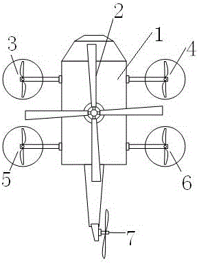
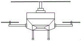
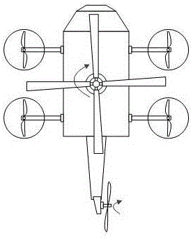
[0036] A hybrid unmanned aerial vehicle with four auxiliary wings, which includes a body, a main rotor, a vertical tail, and four auxiliary rotors; the main rotor is arranged on the upper part of the body, two auxiliary rotors are arranged on both sides of the body, and a vertical tail is arranged on the tail of the body. Tail, the above four auxiliary rotors include left front auxiliary rotor, right front auxiliary rotor, left rear auxiliary rotor and right rear auxiliary rotor. , the right front auxiliary rotor and the left rear auxiliary rotor are reverse propulsion.

[0037] The vertical tail adopts blades with fixed pitch, and the same main rotor also adopts blades with fixed pitch.

[0038]The main rotor is powered by an internal combustion engine, and the vertical tail and four auxiliary rotors are powered by an electric motor.

[0039] The specific analysis of the flight control of this embodiment:

[0040] (1) When the UAV climbs vertically: the main rotor increases...


PUM


Abstract

The invention discloses a hybrid-power unmanned aerial vehicle with four auxiliary wings and a control method thereof. The invention integrates the advantages of a helicopter and four rotor wings and the advantages of oil power and electric power to design a vertical take-off and landing unmanned aerial vehicle which adopts a structure of the helicopter as a main body and adopts the four rotor wings as an auxiliary oil-electricity hybrid-power system. The hybrid-power unmanned aerial vehicle comprises a main rotor wing, a vertical tail wing, a left-front auxiliary rotor wing, a right-front auxiliary rotor wing, a left-rear auxiliary rotor wing and a right-rear auxiliary rotor wing, which are six in number totally. The hybrid-power unmanned aerial vehicle is characterized in that the basic structure of the helicopter is adopted from the whole, but the common fixed-pitch propellers are replaced with the pitch-adjustable propellers of the main rotor wing of the traditional helicopter, and due to the replacement, the main rotor wing loses the function of controlling the flying direction, but the manufacturing cost is effectively reduced; and the control for the flying direction and the maneuvering action of the unmanned aerial vehicle is completed by the vertical tail wing and the four auxiliary rotor wings. The hybrid-power unmanned aerial vehicle disclosed by the invention has the advantages that the main rotor wing adopts an internal combustion engine as power so as to enhance the endurance capability of the unmanned aerial vehicle; and the other rotor wings adopt a brushless motor as power so as to improve the stability and the maneuverability of the unmanned aerial vehicle.

Description

technical field [0001] The invention belongs to the field of aircraft manufacturing, and in particular relates to a hybrid unmanned aerial vehicle with four auxiliary wings and a control method thereof. Background technique [0002] At present, the main factor restricting the development of UAVs is its power system. On rotor UAVs, the commonly used power systems are mainly electric and oil-driven. Electric drones are easy to maneuver and have high sensitivity, but they have poor wind resistance and poor endurance. Especially when the load is heavy, they need to consume a lot of power to overcome gravity; Difficult to operate and poor in sensitivity, the current small oil-powered UAVs mostly use the method of controlling the air intake of the intake valve to control the speed of the blades, and the response to the control signal is relatively sluggish. [0003] Nowadays, both the traditional helicopter architecture and the rapidly popularized multi-rotor architecture have de...

Claims


Application Information

Patent Timeline
IPC IPC(8): B64C27/08B64C27/12B64D35/02
CPCB64C27/08B64C27/12B64D35/02B64U50/00B64U10/10
Inventor 孟光磊潘海兵梁宵田丰喻勇涛薛继佳朱琳琳
Owner SHENYANG AEROSPACE UNIVERSITY
Why Eureka
Try Eureka