

Multi-rotor aircraft
A multi-axis aircraft and airframe technology, applied in the field of aircraft, can solve problems such as poor maneuverability, increased flight resistance, and increased windward area, and achieve the effects of improving safety and reliability, flexible attitude control, and saving energy consumption
- Summary
- Abstract
- Description
- Claims
- Application Information
AI Technical Summary
Problems solved by technology
Method used
Image

Examples
no. 1 example
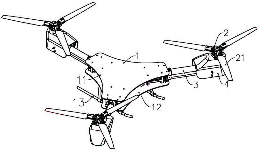
[0029] Such as figure 1 As shown, the aircraft includes a fuselage 1 and a power unit, wherein the fuselage has an upper support plate 11, a lower support plate 12, and a tripod 13 is installed below the lower support plate 12, and the power unit includes three power units 2 arranged symmetrically about the aircraft axis , wherein one power unit 2 is arranged on the axis of the aircraft, and each power unit 2 has three rotors 21 with variable pitch. The power unit 2 is connected to the fuselage 1 through the machine arm 3, and a fairing 4 is arranged on it to protect the internal structure.
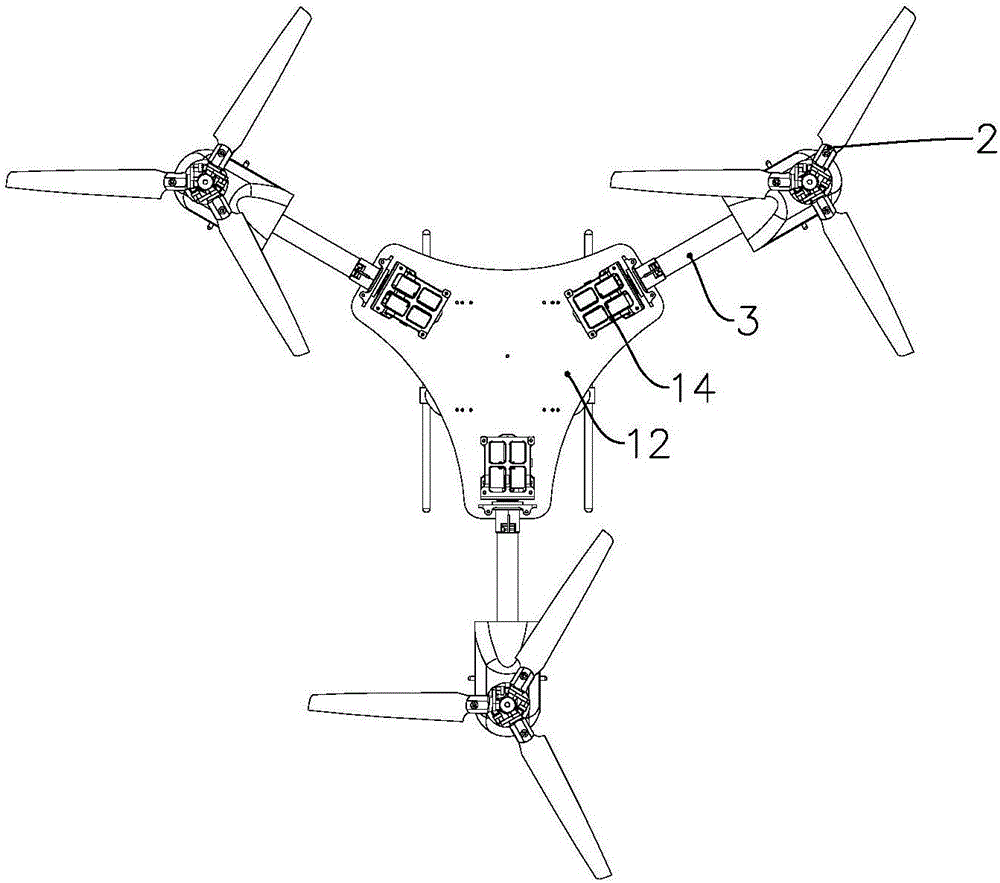
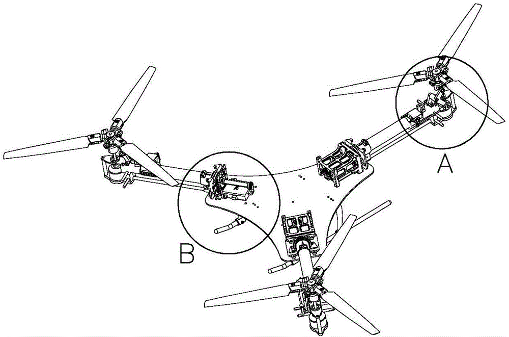
[0030] Such as figure 2 and image 3 As shown, the fixed frame 14 is connected with one end of the machine arm 3, and the fixed frame 14 is firmly connected with the upper support plate 11 and the lower support plate 12 through a plurality of connecting pieces, and each power unit 2 has an inclination to drive it to tilt. Rotating drive mechanisms, wherein each tilting drive mechanism...
no. 2 example
[0035] The structure of this embodiment is substantially the same as that of the first embodiment, but the number of power units is different.
[0036] Such as Figure 6 As shown, the aircraft has four power units 2, and the four power units 2 are symmetrically arranged in a cross shape. Rotating tilting drive mechanism is arranged in each fixed frame 14. Each power unit 2 has a variable-pitch rotor 21 and a variable-pitch control device, and the variable-pitch steering gear is arranged on the machine arm 3 .
no. 3 example
[0038] The structure of this embodiment is substantially the same as that of the first embodiment, but the structure for tilting each power unit is different.
[0039] Such as Figure 7As shown, the power plant of the aircraft includes three power units 2 arranged symmetrically about the axis of the aircraft, one of which is arranged on the axis of the aircraft, and each power unit 2 has three rotors 21 with variable pitch. The power unit 2 is connected to the fuselage 1 through the machine arm 3, and a fairing 4 is arranged on it to protect the internal structure. The fixed mount 14 is connected with one end of the machine arm 3, and the tilting drive mechanism 7 that drives each power unit 2 to tilt is arranged at the central position of the fuselage 1, and the rotating shaft 75 connected with each machine arm 3 passes through the fixed mount 14 and It is rotatably supported by the fixed frame 14, preferably two or more supporting parts on the fixed frame 14, so as to make ...
PUM
 Abstract
Description
Claims
Application Information