Cold plate module cooling system

A heat dissipation system and cold plate technology, applied in the computer field, can solve the problems of heat dissipation solutions that do not consider the large heat of internal modules, ignore the effective processing of liquid cooling plug-ins, and do not take them.

Inactive Publication Date: 2017-07-04
SHANGHAI AEROSPACE SCI & IND ELECTRIC APPLIANCE RES INST
View PDF8 Cites 12 Cited by
  • Summary
  • Abstract
  • Description
  • Claims
  • Application Information

AI Technical Summary

Problems solved by technology

[0002] At present, there are many types of liquid-cooled cold plates for cooling and heat dissipation. The inlet and outlet of the flow channel are in a straight-line state, such as a liquid-cooled cold plate with a composite casting structure disclosed in patent CN102548337, but in some special applications Occasions Because the cold plate needs to be slotted to install the printed board and the height of the components on the printed board is considered, the flow channel entrance and exit cannot be designed for DC, which has application limitations.
[0003] Currently used microchannel cold plates, such as a plate-fin welded electronic cold plate disclosed in patent CN201601941U and a cold plate for electronic components disclosed in patent CN202425269U, the design of the internal flow channel fins is continuous. This design method is relatively stable when the fluid flows, and cannot form a turbulent flow state, the heat dissipation effect is not great, and the guide fin design of the fluid is not considered in the inlet and outlet ports
[0004] Currently used liquid-cooled chassis, such as a new type of high-efficiency cooling chassis and its heat dissipation method disclos

Method used


Image

  • Cold plate module cooling system
  • Cold plate module cooling system
  • Cold plate module cooling system

Examples


Embodiment Construction

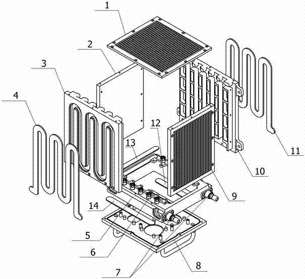
[0038] figure 1 The shown liquid-cooled chassis of the present invention is mainly composed of cover plate (1), left side plate (2), front wall plate (3), front wall plate-runner cover plate (4), base bracket (5), internal fluid Connector (6), external fluid connector (7), rear IO panel (8), right side panel (9), rear wall panel (10), rear wall panel-flow channel cover (11), base bracket- Runner cover plate 1 (12), base support-runner cover plate 2 (13), base support-runner cover plate 3 (14) form. Among them, the inner fluid connector (6) and the outer fluid connector (7) are Y121M-1Z03 and Y121MB-1Z05-A fluid connectors of Guizhou Aerospace Electric Co., Ltd. respectively.

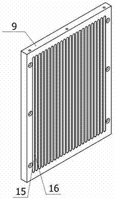
[0039] figure 2 As shown in the schematic diagram of the right side plate (9) of the present invention, the right side plate (9) adopts the cavity (15) formed by digging the plate, and the pattern of cooling fins (16) is formed between adjacent cavities (15), It is convenient to dissipate heat. Cove...


PUM


Abstract

The invention discloses a cold plate module cooling system. The system comprises a liquid cooling case, a cold plate, a fluid connector, an adapter connector and an external connector. The liquid cooling case mainly consists of a cover plate, a left side plate, a front wall plate, a base bracket, a rear IO panel, a right side plate, a rear wall plate and a base bracket-runner cover plate. The front wall plate and the rear wall plate adopt a snake-shaped runner mode, so that a part of heat of a daughter board module is conducted to the front and rear wall plates of the case to carry out cooling, and meanwhile, the case and a runner of the cold plate can be effectively cut through so as to form a fluid flow path which is capable of carrying out cooling effectively. The cold plate adopts a fin type micro-channel manner, so that the high-power cooling of a daughter board is ensured. The system adopts a rear IO architectural mode, so that the external and internal signal transfer processing is improved while the system heat is taken away, and the rear IO architectural mode is a novel architectural processing mode.

Description

technical field [0001] The invention belongs to the field of computer technology. Background technique [0002] At present, there are many types of liquid-cooled cold plates for cooling and heat dissipation. The inlet and outlet of the flow channel are in a straight-line state, such as a liquid-cooled cold plate with a composite casting structure disclosed in patent CN102548337, but in some special applications Occasionally, because the cold plate needs to be slotted to install the printed board and the height of the components on the printed board is considered, the inlet and outlet of the flow channel cannot be designed for DC, which has limitations in application. [0003] Currently used microchannel cold plates, such as a plate-fin welded electronic cold plate disclosed in patent CN201601941U and a cold plate for electronic components disclosed in patent CN202425269U, the design of the internal flow channel fins is continuous. In this design method, the fluid flow is re...

Claims


Application Information

Patent Timeline
IPC IPC(8): G06F1/20
CPCG06F1/20G06F2200/201
Inventor 金旸霖
Owner SHANGHAI AEROSPACE SCI & IND ELECTRIC APPLIANCE RES INST
Why Eureka
Try Eureka