Antenna structure and electronic equipment

A technology of antenna structure and electronic equipment, applied in the field of communication, can solve the problem that the dual-switch antenna cannot effectively take into account multiple antenna modes

Active Publication Date: 2017-07-04
VIVO MOBILE COMM CO LTD
View PDF3 Cites 31 Cited by
  • Summary
  • Abstract
  • Description
  • Claims
  • Application Information

AI Technical Summary

Problems solved by technology

[0003] The embodiment of the present invention provides an antenna structure and electronic equipment to solve the problem that the dual-switch antenna in the prior art cannot effectively take care of multiple antenna modes

Method used


Image

  • Antenna structure and electronic equipment
  • Antenna structure and electronic equipment

Examples


Embodiment 1

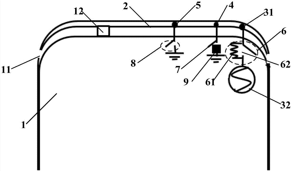
[0022] Such as figure 1 As shown, the embodiment of the present invention provides an antenna structure, which is applied to an electronic device, and the electronic device includes a metal battery cover 1 with a slot structure 11. The antenna structure specifically includes: a slot antenna body 2, a feeder , a first tuning part 4 , a second tuning part 5 , a switch matching circuit 6 , a first switch 7 and a second switch 8 . It should be noted that the slit structure can be arranged at the upper end, lower end, left end or right end of the metal battery cover 1 (electronic device), and the specific position can be set according to actual design requirements, and is not specifically limited here.

[0023] Wherein, the slot antenna body 2 is formed by the first edge of the metal battery cover 1 divided by the slot structure 11 . Further, the antenna structure also includes a plastic support structure, which is located in the slit structure 11. While shielding the slit structu...

Embodiment 2

[0040] Embodiment 2 of the present invention is based on Embodiment 1, in combination with the attached figure 2 The antenna structure of the present invention will be further described.

[0041] Specifically, such as figure 2 As shown, the antenna structure of the embodiment of the present invention includes not only the one listed in the above embodiment: the slot antenna body 2, the feeding part, the first tuning part 4, the second tuning part 5, the switch matching circuit 6, the first switch 7 and the second switch 8, it also includes a resonant matching circuit 9, wherein one end of the resonant matching circuit 9 is connected to the first switch 7, and the other end of the resonant matching circuit 9 is connected to the ground. Adding a resonant matching circuit 9 to the branch where the first tuning part 4 is located can realize the small inductance of the slot antenna body 2 at medium frequency and large inductance at high frequency, thus realizing better debugging...


PUM


Abstract

The invention discloses an antenna structure and electronic equipment. The electronic equipment comprises a metal battery cover with a gap structure. The antenna structure comprises a gap antenna body, a feeding part, a first tuning part, a second tuning, a switch matching circuit, a first switch and a second switch, wherein the gap antenna body is formed from a first edge, cut by the gap structure, of the metal battery cover, the feeding part, the first tuning part and the second tuning are arranged along the gap antenna body, the feeding part comprises a feeding point and a feeding source, the feeding point is connected with the feeding source through the switch matching circuit, the first tuning part is connected with a grounding end through the first switch, and the second tuning part is connected with the grounding end through the second switch. By combined switch-on or switch-off of three switches, multi-frequency band multiplexing is achieved, the antenna performance under a plurality of antenna modes is compatible, and particularly, the coverage of interband carrier aggregation (CA) under different antenna modes is compatible.

Description

technical field [0001] The invention relates to the field of communication technology, in particular to an antenna structure and electronic equipment. Background technique [0002] With the rapid development of mobile terminals, mobile terminals with metal texture will continue to be popular in the future. In the face of various metal structures, the antenna signal of electronic equipment has become a challenge in the industry, especially the multiplexing between antennas covering different frequency bands or different antenna modes. Among them, the U-shaped gap of the metal casing significantly reduces the bandwidth and efficiency of the antenna of the whole device. Taking the traditional dual-switch antenna as an example, the dual-switch antenna scheme can only adjust the resonant mode of the antenna by turning on and off the two control switches; and the modes that the two switches need to cover at the same time include low frequency bands (such as: B12\B5\B8), mid-band...

Claims


Application Information

Patent Timeline
Patent Type & Authority Applications(China)
IPC IPC(8): H01Q1/22H01Q1/50H01Q13/10H01Q23/00
CPCH01Q1/22H01Q1/50H01Q13/103H01Q23/00
Inventor 蒋锐李日辉
Owner VIVO MOBILE COMM CO LTD
Why Eureka
Try Eureka