Ink boxes and printing device

A technology of ink cartridges and mounting parts, applied in the printing field, can solve problems such as disengagement, low assembly reliability, and easy leftward deviation of the joint part 917, and achieve the effect of preventing failure of cooperation and high assembly reliability

Active Publication Date: 2017-07-07
ZHUHAI NINESTAR MANAGEMENT CO LTD
View PDF8 Cites 1 Cited by
  • Summary
  • Abstract
  • Description
  • Claims
  • Application Information

AI Technical Summary

Problems solved by technology

[0003] However, after the ink cartridge 2 is installed on the mounting part 300, the contact pin on the mounting part 300 will give an elastic force to the chip on the ink cartridge 2, and the direction of the elastic force is obliquely upward, and this force causes the joint part 917 to easily deflect to the left. shift, causing the failure of the cooperation between the engaging portion 917 and the mounting hole, causing the ink cartridge 2 to be detached from the mounting portion 300
Therefore, when the ink cartridge 2 and the mounting portion 300 adopt this mounting structure, the assembly reliability of the two is low.

Method used


Image

  • Ink boxes and printing device
  • Ink boxes and printing device
  • Ink boxes and printing device

Examples


Embodiment 1

[0079] Installation department:

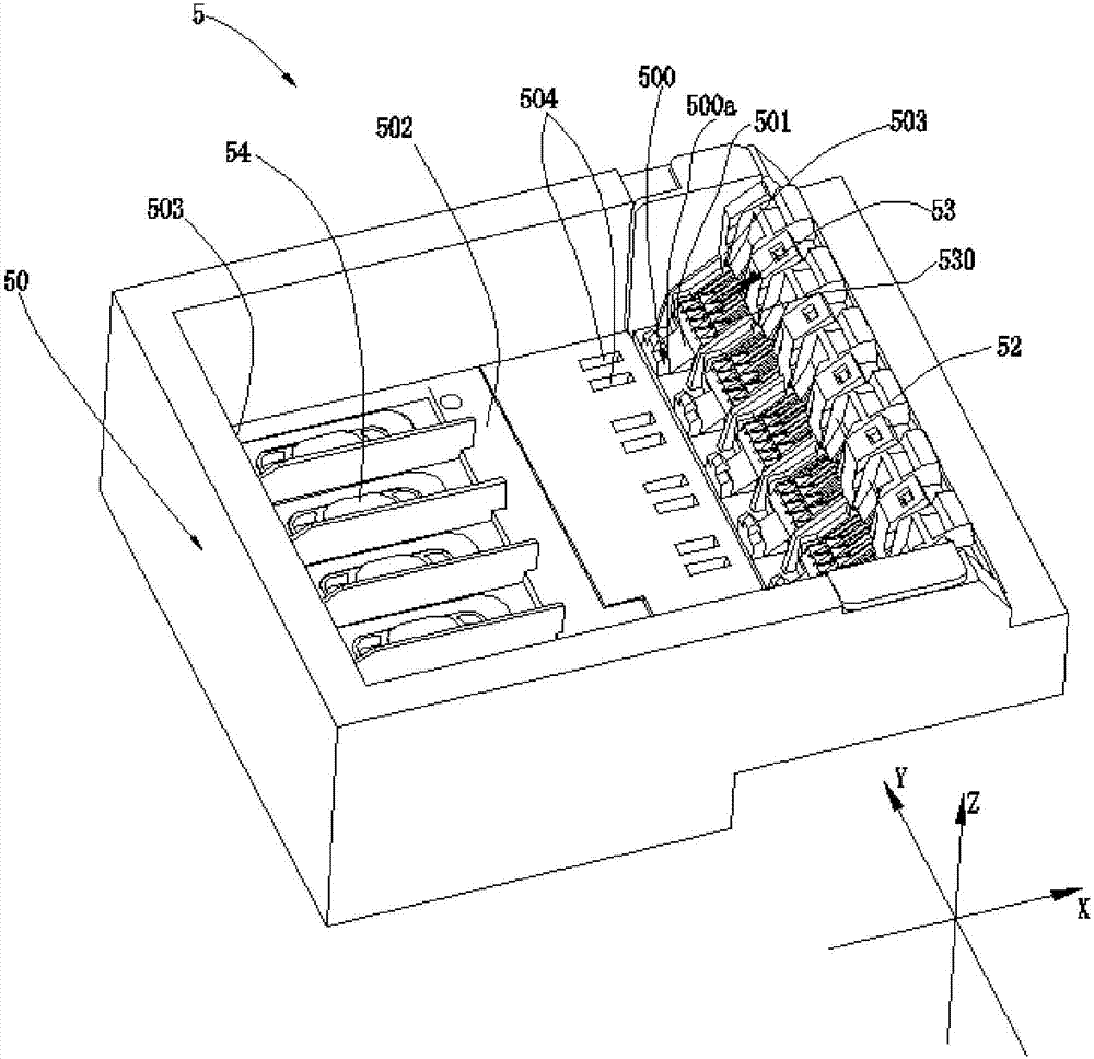
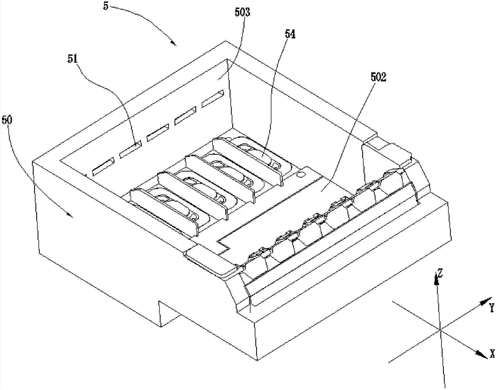
[0080] The installation part is used to install one or more ink cartridges, such as figure 2 and image 3 The shown installation part 5 can install a plurality of ink cartridges 4, and a plurality of installation positions corresponding to each ink cartridge 4 are set on the installation part 5, for example, 6 ink cartridges can be installed, and the installation part 5 has 6 installation positions. The mounting part 5 has a mounting part bracket 50 , a card slot 51 , a lever 52 , an electrical connection part 53 and an ink tube 54 . The mounting bracket 50 includes a protrusion 500 , a first hole 501 , a bottom wall 502 and two side walls 503 . Mounting part bracket 50 can also be provided with figure 2 The second hole 504 is shown, and the second hole 504 may not be provided. It can be understood that the "first holes" and "second holes" mentioned here are not limited to the number of holes, for example, there may be multiple first hol...

Embodiment 2

[0102] Compared with Embodiment 1, the difference of this embodiment lies in that the structures of the installation part 5 and the engaging mechanism are different.

[0103] Specifically, this installation portion 5 has a plurality of installation positions for installing the ink cartridge 4, such as Figure 10 As shown, the mounting part 5 has 4 mounting positions. The protrusions 500 of the 4 installation positions are integrated, and the first hole 501 is also integrated, that is, the protrusions 500 of the 4 installation positions are connected together, and there is no difference due to the installation positions of different ink cartridges 4. Split settings. The first holes 501 are also connected together and not separated.

[0104] In this embodiment, the ink supply needle 55 can also be used to replace the ink tube 54 in the first embodiment, the ink supply needle 55 can be inserted into the interior of the ink cartridge 4, and the ink can flow into the print head t...

Embodiment 3

[0113] Compared with the first embodiment, the difference of this embodiment is that both the joint part 46 and the elastic part 47 cooperate with the second hole 504 to realize the installation between the ink cartridge 4 and the installation part 5 .

[0114] Specifically, such as Figure 14 , Figure 14a As shown, the second hole 504 has a first inner wall 504a and a second inner wall 504b disposed opposite to each other. The elastic portion 47 can press fit with the second inner wall 504b. If the installation direction of the first inner wall 504a relative to the ink cartridge 4 intersects with the installation direction, the joint 46 can press fit with the first inner wall 504a; The mating surface of the portion 46 can be adjusted to be the first mating surface 56 below the second hole 504 .


PUM


Abstract

The invention relates to the technical field of printing, in particular to ink boxes and a printing device. The ink boxes are mounted on a mounting part provided with mounting holes, the joint surface and the positioning surface opposite to the joint surface. Each ink box comprises an ink box main body, a joint part connected with the ink box main body and elastic part connected with the joint part. The joint parts can stretch into the mounting holes and be in positioning fit with the joint part; and the elastic parts can be connected with the positioning surface in an abutting mode to apply acting force on the joint parts toward the directions of the joint parts. After the joint parts and the mounting part are matched, the elastic parts can apply the acting force on the joint parts to enable the joint parts to be in positioning fit with the joint surface on the mounting part, even if the ink boxes are subjected to the acting force from contact pins, the elastic parts can prevent bustle of the joint parts, and matching failure between the joint parts and the mounting holes is prevented, so that it is guaranteed that the joint parts and the mounting part are assembled together more reliably.

Description

technical field [0001] The present application relates to the technical field of printing, in particular to an ink cartridge and a printing device. Background technique [0002] The ink cartridge is one of the important components of the printing device. When installing the ink cartridge, the ink cartridge can be mounted on the mounting portion of the printing device. like figure 1 As shown, with reference to the patent application whose patent application number is CN201420614406.4, the bottom of the ink cartridge 2 is provided with an engaging portion 917, which can adopt a hook-shaped structure. Correspondingly, an installation hole is provided on the mounting portion 300. Portion 917 can cooperate with this mounting hole. At this time, the chip of the ink cartridge 2 is in close contact with the contact pins on the mounting part 300 . [0003] However, after the ink cartridge 2 is installed on the mounting part 300, the contact pin on the mounting part 300 will give a...

Claims


Application Information

Patent Timeline
Patent Type & Authority Applications(China)
IPC IPC(8): B41J2/175
CPCB41J2/17503B41J2/1752
Inventor 陈伟健
Owner ZHUHAI NINESTAR MANAGEMENT CO LTD
Why Eureka
Try Eureka